Configuring Virtual Circuits
183
N
For specific information about the number of connections supported for each
card, please see the
PathBuilder S700 ATM WAN Access Switch Release Notes
.
Adding Virtual Circuits
To define a new virtual circuit, follow these steps:
1
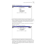
From the Configuration Management menu, select
[2] Manage Circuit
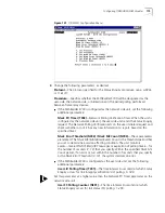
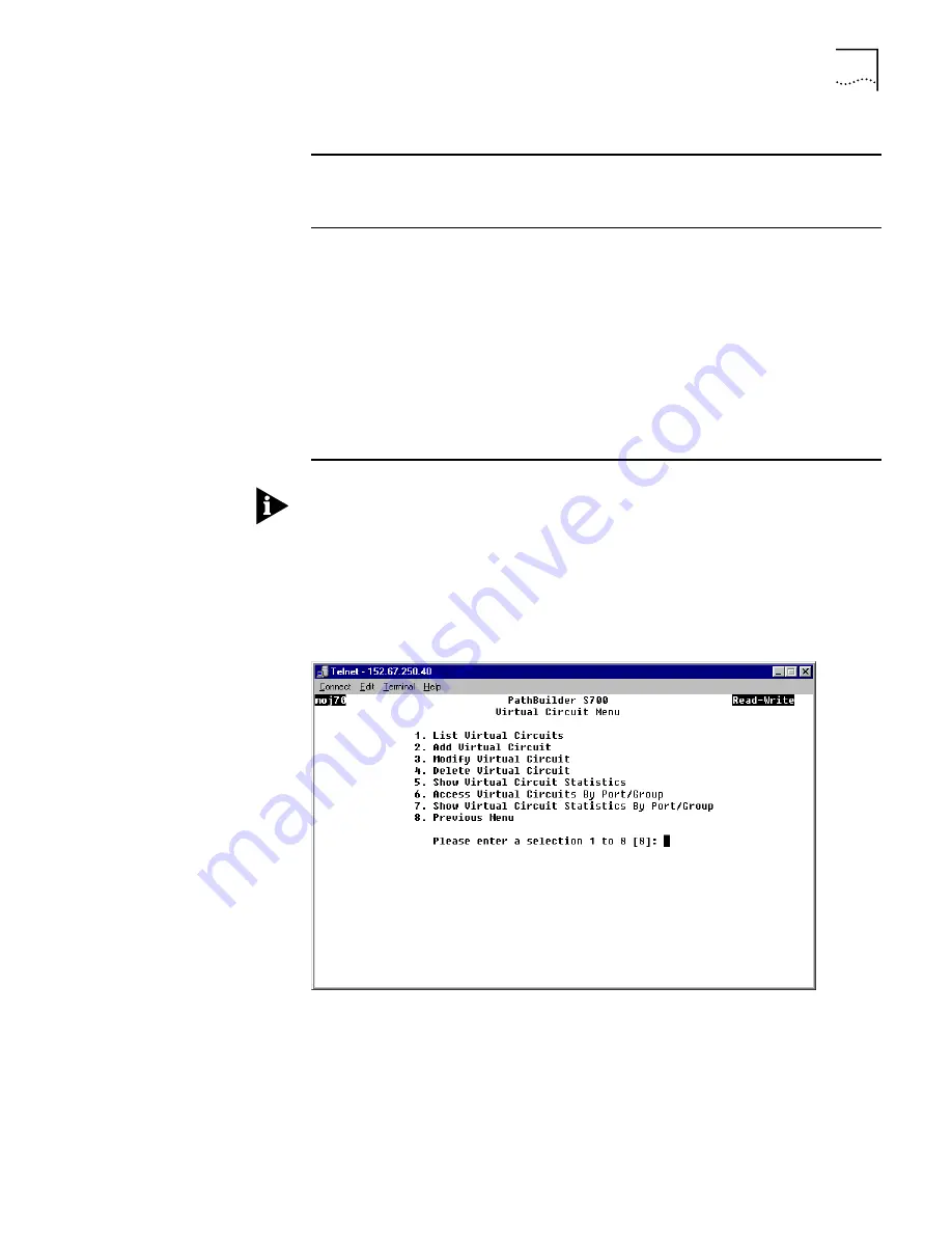
to display
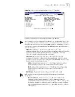
the Virtual Circuit Menu, shown in Figure 144.
Figure 144
Virtual Circuit Menu
2
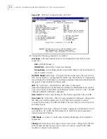
Select
[2] Add Virtual Circuit
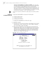
to open the Add Virtual Circuit screen. As shown in
Figure 145, this screen prompts you to enter a description for the circuit.
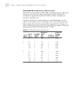
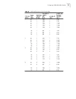
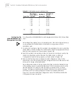
Table 40
Summary of VPI/VCI Ranges and Supported Number of Connections
Card Type
VPI/VCI Range for
VPC only
(Rx = Tx)
VPI/VCI Range for
VCC
(Rx = Tx)
Supported
Number of
Connections
per Module
DS3/E3/OC3/STM-1UNI
VPI = 0... 255
VPI = 0... 255
VCI = 1... N
*
2048
DS1/E1 IMA UNI
VPI = 0... 31
VPI = 0...31
VCI = 1... K
**
256 per IMA
group
Ethernet/QSIM/HSIM/FAM
VPI = 0...255
VCI = 1... N
256
DSX-1 CBR
VPI = 0...255
VCI = 1... N
24 VCs per port
(24 timeslots)
E1 CBR
VPI = 0...255
VCI = 1... N
32 VCs per port
(32 timeslots)
*
N = (2048 - #VPIs-for-VCC) / #VPIs-for-VCC = 2047 for the default 1 VPI-for-VCC
**
K = (32 - #VPIs-for-VCC) / #VPIs-for-VCC = 31 for the default 1 VPI-for-VCC
Summary of Contents for 3C63400-3AC-C - PathBuilder S700 Switch
Page 14: ...xiv CHAPTER SUPPLEMENTARY REGULATORY INFORMATION ...
Page 18: ...4 ABOUT THIS GUIDE ...
Page 28: ...14 CHAPTER 1 SYSTEM DESCRIPTION ...
Page 88: ...74 CHAPTER 3 GETTING STARTED ...
Page 260: ...246 CHAPTER 6 PATHBUILDER S700 DIAGNOSTICS AND PERFORMANCE MONITORING ...
Page 270: ...256 INDEX ...

