Configuring Virtual Circuits
189
Configuring Multicast Source Virtual Circuits
To configure a multicast source circuit, enter a circuit description, as described
under “Adding Virtual Circuits” earlier in this section, then follow these steps from
the Add Virtual Circuit screen shown in Figure 146:
1
Enter
2
to specify the circuit type as
MC Source
.
The Add Virtual Circuit Screen lists the cards available for side A of the circuit, by
slot number, and prompts you to select a slot number, as shown earlier in
Figure 148.
2
Enter the slot number for the card that you want to define as side A of the virtual
circuit.
The default slot number is indicated by an asterisk. To select the default slot
number, simply press [Enter].
After you enter the slot number, the Add Virtual Circuit screen displays the
selected slot number and card type, lists the parameters you will enter for side A of
the circuit, and prompts you to set the first parameter, as shown earlier in
Figure 149. For parameter descriptions, by card, see “Virtual Circuit Parameters”
later in this chapter.
If the card you select has multiple ports, you are prompted to specify the port
number as the first parameter for side A of the circuit.
3
Follow the prompts that appear at the bottom of the screen, pressing [Enter] after
each entry. Default values are listed in square brackets ([ ]) at the end of each
prompt.
Your settings are added to the list of parameters at the top of the screen as you
enter them. You must enter a setting for all the parameters for which you are
prompted in order to add a circuit. Press [Delete] to back up to a previous
selection.
Some parameters that appear on the Add Virtual Circuit screen may not apply to
the particular circuit you are configuring. The system skips any non-applicable
parameters and does not allow you to set them. In addition, certain parameters
may be displayed for information only; you cannot change these read-only values.
After you enter the last parameter for side A, the following prompt appears at the
bottom of the screen:
Enter Admin Status (1 = Out of Service, 2 = In Service)
A multicast source virtual circuit has no side B.
4
Set the administrative status of the circuit as desired.
The following prompt appears at the bottom of the screen:
Is above information correct? (y/n, [y]):
5
Enter
y
to confirm your configuration.
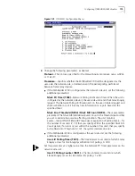
A message confirming that the circuit has been added appears at the bottom of
the screen, as shown in Figure 152.
Summary of Contents for 3C63400-3AC-C - PathBuilder S700 Switch
Page 14: ...xiv CHAPTER SUPPLEMENTARY REGULATORY INFORMATION ...
Page 18: ...4 ABOUT THIS GUIDE ...
Page 28: ...14 CHAPTER 1 SYSTEM DESCRIPTION ...
Page 88: ...74 CHAPTER 3 GETTING STARTED ...
Page 260: ...246 CHAPTER 6 PATHBUILDER S700 DIAGNOSTICS AND PERFORMANCE MONITORING ...
Page 270: ...256 INDEX ...


