5
S
TART
THE
S
WITCH
This chapter summarizes what happens when you
power on your CoreBuilder
®
9000 Enterprise Switch
after you have installed all the Switch components.
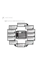
Before you power on the Switch, review the setup
tasks (Figure 22 for the 7-slot chassis and Figure 23
for the 8-slot chassis and the 16-slot chassis) and
make certain that all the tasks have been performed.
Power On the Switch
1
Attach the power supply cables to the connections on
the Switch.
2
Plug the power cord into the electrical socket.
3
Turn on the power switch.
4
Watch the LEDs on installed modules
To verify that the CoreBuilder 9000 Enterprise Switch
modules have been installed correctly, examine the
LED status on each module. To obtain information
about a module’s LEDs and status indicators, see the
User Guide
,
Getting Started Guide
, or
Quick Start
Guide
specific to that module.
What Occurs During Startup
After you turn on the power switch, the following
occurs:
■
The power supplies begin operating.
■
The fans start rotating.
■
The Enterprise Management Engine LEDs blink
green.
Table 8 shows the sequence of characters that appear
on the EME LED character display during a Switch
power-on.
Table 8
The EME LED Character Display During Power-on
Characters in Display Indication
random characters
Power-on has begun.
none (blank display)
Power-on continues.
Diag
The EME is running self-diagnostic
tests.
Cksm
The EME is calculating the checksum
value.
Stby
The EME is in standby mode, if it is a
backup.
Rdy
The EME is active and ready, if it is a
master.
Summary of Contents for 3CB9E7 - CoreBuilder 9000 Chassis Switch
Page 54: ...54 CHAPTER 4 COREBUILDER 9000 ENTERPRISE SWITCH MODULES...
Page 60: ...60 CHAPTER 5 START THE SWITCH...
Page 74: ...74 CHAPTER 7 MAINTENANCE FOR THE 7 SLOT CHASSIS...
Page 88: ...88 CHAPTER 8 MAINTENANCE FOR THE 8 SLOT CHASSIS AND THE 16 SLOT CHASSIS...
Page 96: ...96 APPENDIX A SPECIFICATIONS...
Page 112: ...112 APPENDIX C INTELLIGENT POWER SUBSYSTEM...
Page 118: ...118 APPENDIX D TECHNICAL SUPPORT...

