70
C
HAPTER
7: M
AINTENANCE
FOR
THE
7-S
LOT
C
HASSIS
7
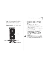
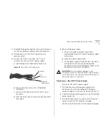
Insert each of the three end wires into the slots of the
DC input connector (Figure 31).
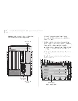
Figure 31
–48-volt DC Power Supply Labels
8
Using a slotted-blade screwdriver, secure each wire to
the DC input connector.
9
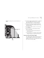
Attach the other end of the 8 AWG gauge wires to
the building’s DC power source, then verify that all
connections at the power supply and the power
source are security attached.
WARNING:
Make certain that the polarity orientation
from the DC power source to the –48-volt DC power
supply connector is the same.
10
Turn on the building’s power source circuit breaker
that connects to the –48-volt DC power supply.
11
Set the power supply’s Standby/On switch to the On
(
) position and follow the normal operating
procedure for your CoreBuilder 9000 7-slot chassis.
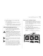
Removing and Replacing a Fan Tray
This section describes how to remove and then
replace a fan tray for the 7-slot chassis:
CAUTION:
The CoreBuilder 9000 7-slot Switch
sends a fan fault message when one fan fails in the
fan tray. However, the Switch can continue to run if
one fan fails in the fan tray. If a second or third fan
fails, in that fan tray, no trap message is generated.
Replace the fan tray within 48 hours of receiving
the trap message or contact your service
representative.
Run the 7-slot Switch with all four
fans operating in the fan tray.
You can remove the fan trays and then install them
without powering off the Switch. This is called
hot
swapping
.
There are no user-serviceable parts on either the
load-sharing power supplies or on the fan trays. If
these components fail, remove them as described
here and return the components to your supplier.
Keep replacement power supply units and fan trays at
your site so that they are available if needed.
STANDBY
ON
-48V
0V
INPUT RATING
-48 V /27A
DC
power source
8 AWG
gauge wires
Summary of Contents for 3CB9E7 - CoreBuilder 9000 Chassis Switch
Page 54: ...54 CHAPTER 4 COREBUILDER 9000 ENTERPRISE SWITCH MODULES...
Page 60: ...60 CHAPTER 5 START THE SWITCH...
Page 74: ...74 CHAPTER 7 MAINTENANCE FOR THE 7 SLOT CHASSIS...
Page 88: ...88 CHAPTER 8 MAINTENANCE FOR THE 8 SLOT CHASSIS AND THE 16 SLOT CHASSIS...
Page 96: ...96 APPENDIX A SPECIFICATIONS...
Page 112: ...112 APPENDIX C INTELLIGENT POWER SUBSYSTEM...
Page 118: ...118 APPENDIX D TECHNICAL SUPPORT...


