background image

Quick Start Guide

3Com Wireless
802.11a Outdoor Building-to-Building 
Bridge and Access Point

3CRWEASYA73 / WL-575

The 3Com WL-575 802.11a Outdoor Building-to-Building Bridge and Access Point provides IEEE 
802.11a or 802.11b/g wireless access to the network. The bridge offers a fast, reliable, and cost-
effective solution for connectivity between remote Ethernet wired LANs or to provide Internet access 
to an isolated site. 

Power is supplied by Power Over Ethernet (PoE) using a:

3Com propriety PoE Injector (output: 48V 60W)

About This Guide

This Quick Start Guide describes the basic installation of the bridge. It covers the following topics:

3Com WL-575 Outdoor Building-to-Building Bridge and Access Point

Observing Safety Precautions

Step 1: Unpacking the Bridge

Step 2: Preparing for Installation

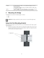
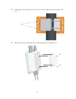
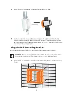
Step 3: Mounting the Bridge

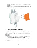
Step 4: Connecting External Antennas

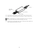
Step 5: Connecting Cables

Step 6: Connecting the Power (PoE Injector)

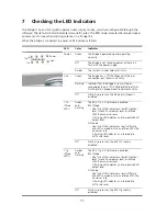
Step 7: Checking the LED Indicators

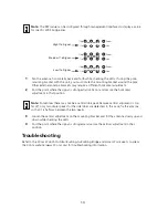
Step 8: Aligning Antennas

Troubleshooting

Summary of Contents for 3CRWEASYA73 - 11a 54 Mbps Wireless LAN Outdoor

Page 1: ...ss to an isolated site Power is supplied by Power Over Ethernet PoE using a 3Com propriety PoE Injector output 48V 60W About This Guide This Quick Start Guide describes the basic installation of the bridge It covers the following topics 3Com WL 575 Outdoor Building to Building Bridge and Access Point Observing Safety Precautions Step 1 Unpacking the Bridge Step 2 Preparing for Installation Step 3 ...

Page 2: ...ategory 5e cable or better with straight through signaling and standard RJ 45 connectors to connect the bridge to the switch on the network The bridge should be powered via proprietary Power Over Ethernet PoE power injector LEDs The LEDs indicate power and activity See Checking the LED Indicators on page 11 for details Antenna Connectors Three N type female antenna connectors allow you to connect ...

Page 3: ...h location Additionally observe the following items before mounting or connecting the bridge Grounding Point In the event of electrostatic shock the connection of an insulated cable to the grounding point to an earthed point protects the unit from excessive electrical discharge A grounding screw is provided in the package contents Integrated Antenna Built in 5 0 GHz flat panel high gain antenna WA...

Page 4: ...e bracket may need to be rotated around the pole during the antenna alignment process IP Address Record the bridge MAC address in a safe place before the bridge is installed in a hard to reach location The MAC address is printed on the back of the bridge Additional IP address labels are shipped with the bridge Location The WL 575 bridge must only be installed outdoors It is not for indoor use The ...

Page 5: ...5 2 Fit the edges of the V shaped part into the slots in the rectangular plate and tighten the nuts 3 Attach the adjustable rectangular plate to the bridge with the supplied screws Slots ...

Page 6: ...the antenna polarization direction all antennas in a link must be mounted with the same polarization Using the Wall Mounting Bracket Perform the following steps to mount the unit to a wall using the wall mounting bracket 1 Always attach the bracket to a wall with the flat side flush against the wall see following figure CAUTION The wall mounting bracket does not allow the bridge s integrated anten...

Page 7: ...link or access point operation you may need to mount external antennas and connect them to the bridge Typically a bridge link requires a 5 0 GHz antenna and access point operation a 2 4 GHz antenna WL 575 units acting as managed APs also require an external antenna for 2 4 GHz operation Perform these steps 1 Mount the external antenna to the same supporting structure as the bridge within 3 m 10 ft...

Page 8: ... screw on the unit NOTE When you have connected external antennas be sure to use the management interface to configure the bridge for correct antenna operation CAUTION Be sure that grounding is available and that it meets local and national electrical codes For additional lightning protection use lightning rods lightning arrestors or surge suppressors RF Coaxial Cable 2 4 GHz External Omnidirectio...

Page 9: ...cable for 10 100BASE TX connections CAUTION Do not install the power injector outdoors The unit is for indoor installation only NOTE The wireless bridge s Ethernet port does not support Power over Ethernet PoE based on the IEEE 802 3af standard Do not try to power the unit by connecting it directly to a network switch that provides IEEE 802 3af PoE Always connect the unit to the included power inj...

Page 10: ...heck the LED on top of the power injector to be sure that power is being supplied to the wireless bridge through the Ethernet connection NOTE For International use you may need to change the AC line cord You must use a line cord set that has been approved for the socket type in your country Input Output AC power Power LED indicator Input from Ethernet Hub Switch Output to Bridge ...

Page 11: ...present or the Ethernet LAN port is disabled 11a Three LEDs Green and Flashing The 802 11a 5 3 GHz radio is enabled RSSI Mode One fully lit LED indicates a low RSSI output level two LEDs a medium level and three LEDs the maximum level A flashing LED indicates an intermediate RSSI output level AP Mode One fully lit LED indicates a low traffic rate two LEDs a medium rate and three LEDs the maximum r...

Page 12: ... bridge nodes must be aligned with the root bridge antenna The alignment process is the same as in point to point links but only the bridge node end of the link requires the alignment The signal strength LEDs indicate the received radio signal strength for a particular bridge link The more LEDs that turn on the stronger the signal Alternatively you can monitor the Receive Signal Strength Indicator...

Page 13: ... where the signal is strongest and secure the vertical adjustment in that position Troubleshooting Refer to the 3Com WL 575 Outdoor Building to Building Bridge and Access Point User s Guide or the 3Com website www 3Com com for troubleshooting information Note The RSSI value can be configured through management interfaces to display a value for specific WDS bridge links Note Sometimes there may not...

Page 14: ...of 20 cm approximately 8 in The installer of this radio equipment must ensure that the antenna is located or pointed such that it does not emit RF field in excess of Health Canada limits for the general population consult Safety Code 6 obtainable from Health Canada s website www hc sc gc ca rpb This equipment complies with IC radiation exposure limits set forth for an uncontrolled environment End ...

Page 15: ...try to correct the interference by one or more of the following measures Reorient or relocate the receiving antenna Increase the separation between the equipment and receiver Connect the equipment into an outlet on a circuit different from that to which the receiver is connected Consult the dealer or an experienced radio TV technician for help The user may find the following booklet prepared by th...

Page 16: ...unication To prevent radio interference to the licensed service this device is intended to be operated indoors and away from windows to provide maximum shielding Equipment or its transmit antenna that is installed outdoors is subject to licensing Pour empecher que cet appareil cause du brouillage au service faisant l objet d une licence il doit etre utilize a l interieur et devrait etre place loin...

Page 17: ...den Anf orderungen und den übrigen einschlägigen Bestimmungen der Richtlinie 1999 5 EG bef indet Eesti Estonian Käesolev aga kinnitab 3Com Corporation seadme RLAN device v astav ust direktiiv i 1999 5 EÜ põhinõuetele ja nimetatud direktiiv ist tulenev atele teistele asjakohastele sätetele English Hereby 3Com Corporation declares that this RLAN device is in compliance with the essential requirement...

Page 18: ...ikalav imus ir kitas 1999 5 EB Direktyv os nuostatas Nederlands Dutch Hierbij v erklaart 3Com Corporation dat het toestel RLAN device in ov ereenstemming is met de essentiële eisen en de andere relev ante bepalingen v an richtlijn 1999 5 EG Malti Maltese Hawnhekk 3Com Corporation jiddikjara li dan RLAN device jikkonf orma mal ti ijiet essenzjali u ma provv edimenti o rajn relev anti li hemm f id D...

Page 19: ... ensure the Bridge Access Point device s are properly configured for European Community operation This device employs a radar detection feature required for European Community operation in the 5GHz bands This feature must be activated in order to use ad hoc operation The presence of nearby radar operation may result in interruption in communications of this device It will be necessary to configure...

Page 20: ...r 10015231 Revision AA Published December 2007 Safety Information AC Power Adapter Input 100 240 AC 50 60 Hz Output 48 VDC 1 2 A Power consumption 13 2 watts Unit Power Supply PoE input 48 VDC 0 6 A maximum Power consumption 28 watts maximum Physical Size 19 5 x 19 x 7 4 cm 7 68 x 7 48 x 2 91 in Weight 1 54 kg 3 4 lbs Temperature Operating 40 to 60 C 40 to 140 F non condensing 5 to 50 C Storage 55...

Reviews: