background image

3

Observing Safety Precautions

This equipment must be installed in compliance with local and national building codes, regulatory 
restrictions, and FCC rules. For the safety of people and equipment, only professional network personnel 
should install the access point.

1

Unpacking the Access Point

Make sure that you have the following items, which are included with the access point:

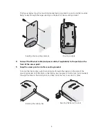
Two external 2.4 GHz and 5.3 GHz dual-band antennas

Mounting bracket (attached to the access point)

Wall-mounting hardware:

Locking bar (used for securing a wall- or ceiling-mounted installation)

Two sheet metal screws

Two thread screws

Two wall anchors

Four adhesive rubber feet (used for a flat-surface installation).

2

Preparing for Installation

It is advisable to connect the power (if using an external power supply) and check the Ethernet cables 
and LEDs before installing the access point in a hard-to-reach location. Additionally, observe the 
following items before mounting or connecting the access point:
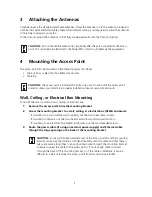
WARNING:


 To comply with FCC radio frequency (RF) exposure limits, a minimum body-to-

antenna distance of 20 cm (8 in.) must be maintained when the access point is operational.

WARNING:

  To avoid possible injury or damage to equipment, you must use power supply equipment 

that is safety certified according to UL, CSA, IEC, or other applicable national or international safety 
requirements for the country of use. All references to power supply in this document refer to equipment 
meeting these requirements.

Installation Item

Description

Switch port

3Com recommends that you install and configure the 3Com Wireless LAN switch 
before installing the access point. Set the port type on the switch to an AP2750 
access point.

Cabling

Make sure that standard Category 5 cable with straight-through signaling is 
installed at the site before you install the access point.
Make sure that the cable is highly flexible and that there is no extra covering on the 
RJ-45 connector that could prevent the cable from being routed through the 
mounting bracket.

Power Requirements

Power can be supplied via an 802.3af Power Over Ethernet (PoE)-compliant device 
or by an external power supply with a minimum 5v @ 2.0 amp.
If using an external power supply, make sure the power outlet is accessible. The 
power supply plug is the only means of disconnecting the access point from power. 

MAC Address

Record the access point MAC address in a safe place before the access point is 
installed in a hard-to-reach location.
The MAC address is printed on the back of the access point. Additional MAC 
address labels are shipped with the access point.

Summary of Contents for 3CRWX275075A - Wireless LAN Managed Access Point...

Page 1: ... point 3Com WX4400 3Com WX1200 Power can be supplied via Power Over Ethernet PoE or by an external power supply Four 3Com PoE devices supply power to the access point 3Com PoE Injector 3Com 4400PWR PoE Switch 3Com Multi port PoE power supply 3Com WX1200 About This Guide This Quick Start Guide describes the basic installation of the access point It covers the following topics 3Com AP2750 Managed Ac...

Page 2: ...d standard RJ 45 connectors to connect the access point to the switch on the network LEDs The LEDs indicate power and activity See Checking the LED Indicators on page 7 for details Antenna Connectors Two SMA female antenna connectors allow you to connect antennas that operate in 2 4 GHz and 5 3 GHz bands Reset Button The reset button is accessible from the back of the access point as well as throu...

Page 3: ...mage to equipment you must use power supply equipment that is safety certified according to UL CSA IEC or other applicable national or international safety requirements for the country of use All references to power supply in this document refer to equipment meeting these requirements Installation Item Description Switch port 3Com recommends that you install and configure the 3Com Wireless LAN swi...

Page 4: ...ews and two wall anchors If mounting to an electrical box NEMA enclosure use the two threaded screws 3 Route the power cable if using an external power supply and Ethernet cable through the large opening on the back of the mounting bracket CAUTION Do not handle the antenna tips especially after they are connected to the access point This could lead to electrostatic discharge ESD which could damage...

Page 5: ...ess point 5 Snap the access point onto the mounting bracket To install the locking bar push the locking bar through the opening in the side of the mounting bracket until the hole on the locking bar is exposed Insert a lock not provided through the hole on the locking bar and then close the lock to secure it in place Installing the mounting bracket Routing a cable Cradle Inserting the locking bar S...

Page 6: ... LAN Switch port or indirectly to 3Com Wireless LAN switches through an intermediate Layer 2 or Layer 3 network In either case use Category 5 cable with straight through signaling for each access point connection To connect the access point directly to a 3Com Wireless LAN Switch configure the switch port as an AP2750 access point and then insert the cable into the switch and verify the link To con...

Page 7: ...ccess point is powered up and operating normally The access point is not receiving power or there is a fault with the power supply 11a Green Off The access point has WLAN frame transmission over the 802 11a 5 3 GHz radio band No link is present 11b g Green Off The access point has WLAN frame transmission over the 802 11g 2 4 GHz radio band No link is present 100 Green Off The access point has a 10...

Page 8: ...2 July 1999 on the limitation of exposure of the general public to electromagnetic fields 0 Hz to 300 GHz USA RADIO FREQUENCY REQUIREMENTS This device is for indoor use only when using channels 36 40 44 or 48 in the 5 15 to 5 25 GHz frequency range High power radars are allocated as primary users of the 5 25 to 5 35 GHz and 5 65 to 5 85 GHz bands These radar stations can cause interference with an...

Page 9: ...d Access Point 3CRWX275075A or the substitution or attachment of connecting cables and equipment other than specified by 3Com The correction of interference caused by such unauthorized modification substitution or attachment will be the responsibility of the user MANUFACTURER S DECLARATION OF CONFORMITY 3Com Corporation 350 Campus Drive Marlborough MA 01752 3064 USA 800 527 8677 Date November 8 20...

Page 10: ... indoors and away from windows to provide maximum shielding Equipment or its transmit antenna that is installed outdoors is subject to licensing Pour empecher que cet appareil cause du brouillage au service faisant l objet d une licence il doit etre utilize a l interieur et devrait etre place loin des fenetres afin de Fournier un ecram de blindage maximal Si le matriel ou son antenne d emission es...

Page 11: ...en ja sitä koskevien direktiivin muiden ehtojen mukainen Dutch Hierbij verklaart 3Com Corporation dat het toestel RLAN device in overeenstemming is met de essentiële eisen en de andere relevante bepalingen van richtlijn 1999 5 EG Bij deze verklaart 3Com Corporation dat deze RLAN device voldoet aan de essentiële eisen en aan de overige relevante bepalingen van Richtlijn 1999 5 EC French Par la prés...

Page 12: ...jiddikjara li dan RLAN device jikkonforma mal ntigijiet essenzjali u ma provvedimenti onrajn relevanti li hemm fid Dirrettiva 1999 5 EC Estonian Käesolevaga kinnitab 3Com Corporation seadme RLAN device vastavust direktiivi 1999 5 EÜ põhinõuetele ja nimetatud direktiivist tulenevatele teistele asjakohastele sätetele Hungarian Alulírott 3Com Corporation nyilatkozom hogy a RLAN device megfelel a vona...

Page 13: ... user must cease operating the Managed Access Point at that location and consult the local technical support staff responsible for the wireless network The 5GHz Turbo mode feature is not allowed for operation in any European Community country This device must be used with the radar detection feature required for European Community operation in the 5GHz bands This device will avoid operating on a c...

Page 14: ...ASSOCIATED STATION DEVICES 1 After initial installation use the 5GHz Statistics Window to view all currently associated Wireless station devices operating on 5GHz channels Check current transmit receive link rates of each station by clicking on the applicable underlined links The highest possible link rate is 54Mbps Note 108Mbps Turbo operation in 5GHz is not allowed in the European Community CHEC...

Page 15: ...dB setting are now lower than the maximum possible values the 6dB power reduction is not necessary Please change the Transmit Power Level setting back to 3dB as explained in step 3 No further action is required OR equal to the maximum possible link rate values the 6dB reduction has no adverse affect on operation and further reduction is not necessary Retain the 6dB setting No further action is req...

Page 16: ...rights reserved 3Com and the 3Com logo are registered trademarks of 3Com Corporation All other company and product names may be trademarks of the respective companies with which they are associated DIA27507 5AAA 02 Published December 2004 ...

Reviews: