Settings
3Com
®
AirProtect
Planner
User
Guide
98
•
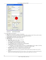
Tolerance:
Specify
the
tolerance
in
the
range
of
1
to
20.
For
example,
if
you
click
the
mouse
20
pixels
away
from
the
declared
tolerance
value,
the
cursor
will
select
the
device.
•
Angular
Line
Settings:
Default
Width:
Specify
the
desired
width
to
draw
all
angular
lines.
•
Hollow
Object
Settings:
Default
Thickness:
Specify
the
desired
thickness
to
draw
all
hollow
objects.
8.2.2
Preferences:
AP
Views
Go
to
Settings
Æ
Preferences
Æ
AP
Views
,
the
AP
Views
tab
appears.
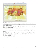
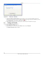
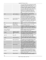
Figure 130.
Preferences – AP Views
The
screen
allows
you
to
define
AP
and
Channel
views
settings:
•
AP
View
Settings
¾
Ambient
Noise:
Specify
a
value
to
calculate
the
SINR
value
with
respect
to
the
total
channel
interference
across
the
layout.
Recommended:
Do
not
change
the
Ambient
Noise
values
unless
you
are
very
sure
of
the
environment
properties.
¾
Coverage
Estimation
Thresholds:
Specify
the
threshold
for
the
coverage
outlines
shown
for
APs
while
dragging
those
on
the
layout.
Enter
the
values
in
the
range
‐
100
to
‐
10
dBm.
Planner
shows
the
areas
covered
in
the
form
of
concentric
spheres,
depending
upon
the
values
specified
for
the
regions.
You
can
have
a
maximum
of
four
separate
regions.
Planner
assumes
an
Omni
‐
directional
antenna
in
this
case.
•
Channel
View
Settings
¾
Availability
Threshold:
Define
a
threshold
value
for
the
Channel
View.
Planner
does
not
consider
a
signal
below
this
value,
while
calculating
the
channel
at
a
location.
The
value
should
be
in
the
range
‐
150
to
‐
20.
¾
See
Channel
Interference
for:
Allows
you
to
view
channel
interference
for
the
selected
channels.
8.2.3
Preferences:
Sensor
Views
Go
to
Settings
Æ
Preferences
Æ
Sensor
Views
,
the
Sensor
Views
tab
appears.


