


114
C
HAPTER
6: IP R
OUTING
P
ROTOCOL
O
PERATION
Example: Typical RIP
Configuration
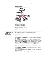
Networking Requirements
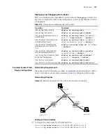
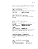
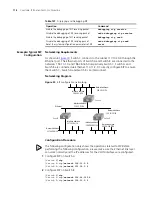
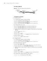
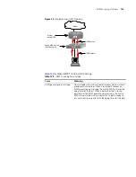
As shown in
Figure 30
, Switch C connects to the subnet 117.102.0.0 through the
Ethernet port. The Ethernet ports of Switch A and Switch B are connected to the
networks 155.10.1.0 and 196.38.165.0 respectively. Switch C, Switch A and
Switch B are connected via Ethernet 110.11.2.0. Correctly configure RIP to ensure
that Switch C, Switch A and Switch B can interconnect.
Networking Diagram
Figure 30
RIP configuration networking
Configuration Procedure
The following configuration only shows the operations related to RIP.
Before
performing the following configuration, please make sure the Ethernet link layer
can work normally and the IP addresses for the VLAN interfaces are configured.
1
Configure RIP on Switch A
[Switch A]
rip
[Switch A-rip]
network 110.11.2.0
[Switch A-rip]
network 155.10.1.0
2
Configure RIP on Switch B
[Switch B]
rip
[Switch B-rip]
network 196.38.165.0
[Switch B-rip]
network 110.11.2.0
Enable the debugging of RIP receiving packet
debugging rip receive
Disable the debugging of RIP receiving packet
undo debugging rip receive
Enable the debugging of RIP sending packet
debugging rip send
Disable the debugging of RIP sending packet
undo debugging rip send
Reset the system configuration parameters of RIP
reset
Table 121
Displaying and Debugging RIP
Operation
Command
Ethernet
Network address:
110.11.2.2/24
Network address:
117.102.0.0/16
Network address:
196.38.165.0/24
Interface address:
110.11.2.1/24
Interface address:
117.102.0.1/16
Interface address:
155.10.1.1/24
Network address:
155.10.1.0/24
Interface address:
196.38.165.1/24
SwitchA
SwitchB
SwitchC
Summary of Contents for 400 Family
Page 12: ......
Page 16: ...14 ABOUT THIS GUIDE ...
Page 58: ...56 CHAPTER 2 PORT OPERATION ...
Page 68: ...66 CHAPTER 3 VLAN OPERATION ...
Page 98: ...96 CHAPTER 5 NETWORK PROTOCOL OPERATION ...
Page 124: ...122 CHAPTER 6 IP ROUTING PROTOCOL OPERATION ...
Page 156: ...154 CHAPTER 8 ACL CONFIGURATION ...
Page 218: ...216 CHAPTER 11 802 1X CONFIGURATION ...
Page 298: ...296 CHAPTER 13 PASSWORD CONTROL CONFIGURATION OPERATIONS ...
Page 336: ...334 APPENDIX B RADIUS SERVER AND RADIUS CLIENT SETUP ...


