


20
C
HAPTER
1: G
ETTING
S
TARTED
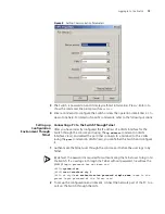
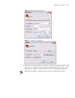
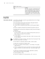
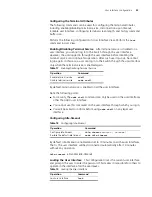
Figure 6
Setting up the Configuration Environment through Telnet
3
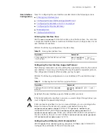
Run Telnet on the PC and enter the IP address of the VLAN connected to the
network port on the PC.
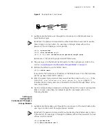
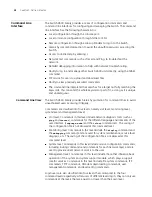
Figure 7
Running Telnet
4
The terminal displays
Login authentication
and prompts the user to enter the
logon password. After you enter the correct password, it displays the command
line prompt (such as
<4500>
). If the prompt
All user interfaces are used,
please try later!
appears, too many users are connected to the Switch
through Telnet. At most five Telnet users are allowed to log on to the SW4500
Switch simultaneously.
5
Use the corresponding commands to configure the Switch or to monitor the
running state. Enter
?
to view online help. For details of specific commands, refer
to the following chapters.
When configuring the Switch through Telnet, do not modify the IP address of the
Switch unnecessarily, for the modification might end the Telnet connection.
By default, when a Telnet user passes the password authentication to log on to the
Switch, the access level for commands will be Level 0.
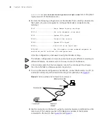
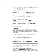
Telneting a Switch Through Another Switch
After a user has logged into a Switch, it is possible to configure another Switch
through the Switch through Telnet. The local Switch serves as Telnet client and the
peer Switch serves as the Telnet server. If the ports connecting these two Switches
are in the same local network, their IP addresses must be configured in the same
network segment. Otherwise, the two Switches must establish a route to
communicate with each other.
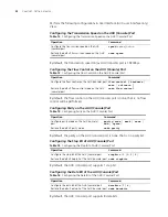
As shown in
Figure 8
, after you Telnet to a Switch, you can run the
telnet
command to log in to, and configure, another Switch.
Workstation
Workstation
Serv er
PC ( for configuring the switch
via Telnet )
Ethernet port
Ethernet
Workstation
Workstation
Serv er
PC ( for configuring the switch
via Telnet )
Ethernet port
Ethernet
Summary of Contents for 400 Family
Page 12: ......
Page 16: ...14 ABOUT THIS GUIDE ...
Page 58: ...56 CHAPTER 2 PORT OPERATION ...
Page 68: ...66 CHAPTER 3 VLAN OPERATION ...
Page 98: ...96 CHAPTER 5 NETWORK PROTOCOL OPERATION ...
Page 124: ...122 CHAPTER 6 IP ROUTING PROTOCOL OPERATION ...
Page 156: ...154 CHAPTER 8 ACL CONFIGURATION ...
Page 218: ...216 CHAPTER 11 802 1X CONFIGURATION ...
Page 298: ...296 CHAPTER 13 PASSWORD CONTROL CONFIGURATION OPERATIONS ...
Page 336: ...334 APPENDIX B RADIUS SERVER AND RADIUS CLIENT SETUP ...


