


SNMP Configuration
261
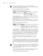
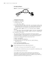
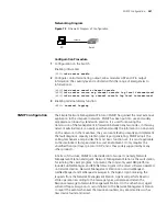
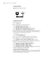
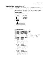
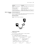
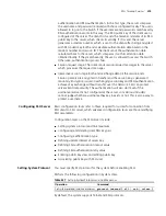
Networking Diagram
Figure 73
Schematic Diagram of Configuration
Configuration Procedure
1
Configuration on the Switch
Enabling info-center
[4500]
info-center enable
2
Configure control terminal log output; allow modules ARP and IP to output
information; the severity
level is restricted within the range of emergencies to
informational.
[4500]
info-center console channel console
[4500]
info-center source arp channel console log level informational
[4500]
info-center source ip channel console log level informational
3
Enabling terminal display function
<4500>
terminal logging
SNMP Configuration
The Simple Network Management Protocol (SNMP) has gained the most extensive
application in the computer networks. SNMP has been put into use and widely
accepted as an industry standard in practice. It is used for ensuring the
transmission of the management information between any two nodes. In this way,
network administrators can easily search and modify the information on any node
on the network. In the meantime, they can locate faults promptly and implement
the fault diagnosis, capacity planning and report generating. SNMP adopts the
polling mechanism and provides the most basic function set. It is most applicable
to the small-sized, fast-speed and low-cost environment. It only requires the
unverified transport layer protocol UDP; and is thus widely supported by many
other products.
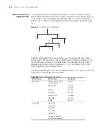
In terms of structure, SNMP can be divided into two parts, namely, Network
Management Station and Agent. Network Management Station is the workstation
for running the client program. At present, the commonly used NM platforms
include Sun NetManager and IBM NetView. Agent is the server software operated
on network devices. Network Management Station can send GetRequest,
GetNextRequest and SetRequest messages to the Agent. Upon receiving the
requests from the Network Management Station, Agent will perform Read or
Write operation according to the message types, generate and return the
Response message to Network Management Station. On the other hand, Agent
will send Trap message on its own initiative to the Network Management Station
to report the events whenever the device encounters any abnormalities such as
new device found and restart.
console
PC
Switch
console
PC
Switch
console
PC
Switch
console
PC
Switch
Summary of Contents for 400 Family
Page 12: ......
Page 16: ...14 ABOUT THIS GUIDE ...
Page 58: ...56 CHAPTER 2 PORT OPERATION ...
Page 68: ...66 CHAPTER 3 VLAN OPERATION ...
Page 98: ...96 CHAPTER 5 NETWORK PROTOCOL OPERATION ...
Page 124: ...122 CHAPTER 6 IP ROUTING PROTOCOL OPERATION ...
Page 156: ...154 CHAPTER 8 ACL CONFIGURATION ...
Page 218: ...216 CHAPTER 11 802 1X CONFIGURATION ...
Page 298: ...296 CHAPTER 13 PASSWORD CONTROL CONFIGURATION OPERATIONS ...
Page 336: ...334 APPENDIX B RADIUS SERVER AND RADIUS CLIENT SETUP ...


