


SNMP Configuration
267
If user disable NMP Agent, it will be enabled whatever
snmp-agent
command is
configured thereafter.
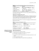
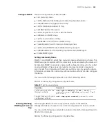
Displaying and
Debugging SNMP
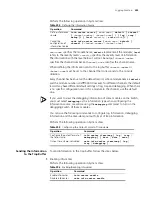
After the above configuration, execute the
display
command in all views to
display the running of the SNMP configuration, and to verify the effect of the
configuration.
Execute the
debugging
command in User View to debug SNMP
configuration.
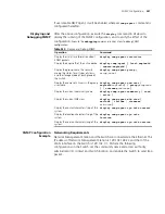
Table 320
Display and Debug SNMP
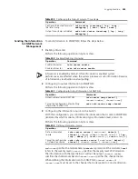
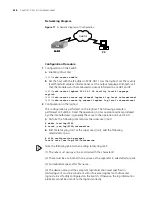
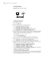
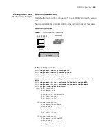
SNMP Configuration
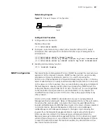
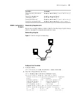
Example
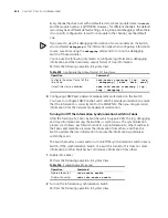
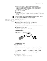
Networking Requirements
Network Management Station and the Switch are connected via the Ethernet. The
IP address of Network Management Station is 129.102.149.23 and that of the
VLAN interface on the Switch is 129.102.0.1.
Perform the following
configurations on the Switch: set the community name and access authority,
administrator ID, contact and Switch location, and enable the Switch to send trap
packet.
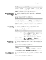
Operation
Command
Display the statistics information about
SNMP packets
display snmp-agent statistics
Display the engine ID of the active device
display snmp-agent { local-engineid
| remote-engineid }
Display the group name, the security
mode, the states for all types of views,
and the storage mode of each group of
the Switch.
display snmp-agent group [
group-name
]
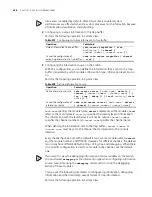
Display the names of all users in the group
user table
display snmp-agent usm-user [
engineid
engineid
] [ group
groupname
] [ username
username
]
Display the current community name
display snmp-agent community [ read
| write ]
Display the current MIB view
display snmp-agent mib-view [
exclude | include | viewname
mib-view
]
Display the contact character string of the
system
display snmp-agent sys-info contact
Display the location character string of the
system
display snmp-agent sys-info
location
Display the version character string of the
system
display snmp-agent sys-info version
Summary of Contents for 400 Family
Page 12: ......
Page 16: ...14 ABOUT THIS GUIDE ...
Page 58: ...56 CHAPTER 2 PORT OPERATION ...
Page 68: ...66 CHAPTER 3 VLAN OPERATION ...
Page 98: ...96 CHAPTER 5 NETWORK PROTOCOL OPERATION ...
Page 124: ...122 CHAPTER 6 IP ROUTING PROTOCOL OPERATION ...
Page 156: ...154 CHAPTER 8 ACL CONFIGURATION ...
Page 218: ...216 CHAPTER 11 802 1X CONFIGURATION ...
Page 298: ...296 CHAPTER 13 PASSWORD CONTROL CONFIGURATION OPERATIONS ...
Page 336: ...334 APPENDIX B RADIUS SERVER AND RADIUS CLIENT SETUP ...


