


60
C
HAPTER
3: VLAN O
PERATION
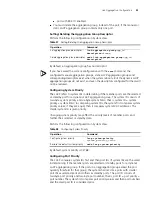
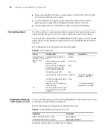
Networking Diagram
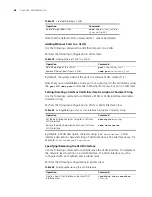
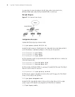
Figure 14
VLAN Configuration Example
1
Configuration Procedure
1
Create VLAN 2 and enter its view.
[4500]
vlan 2
2
Add Ethernet1/0/1 and Ethernet1/0/2 to VLAN2.
[4500-vlan2]
port ethernet1/0/1 to ethernet1/0/2
3
Create VLAN 3 and enter its view.
[4500-vlan2]
vlan 3
4
Add Ethernet1/0/3 and Ethernet1/0/4 to VLAN3.
[4500-vlan3]
port ethernet1/0/3 to ethernet1/0/4
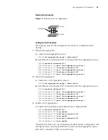
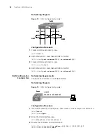
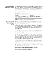
VLAN Configuration
Example Two
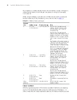
Networking Requirements
Configure an IP address on a VLAN interface.
Networking Diagram
Figure 15
VLAN Configuration Example 2
Configuration Procedure
1
If the VLAN does not currently exist, then create it. This example uses VLAN ID 3.
[4500
]
vlan 3
[4500-vlan3
]
quit
2
Enter the VLAN interface view:
[4500
]
interface vlan-interface 3
3
Provide the IP address and subnet mask:
[4500-Vlan-interface3]
ip address 192.168.1.5 255.255.255
[4500-Vlan-interface3]
quit
VLAN3
Switch
E1/0/3
E1/0/2
VLAN2
VLAN3
E1/0/4
E1/0/1
Switch
VLAN3
Switch
E1/0/3
E1/0/2
VLAN2
VLAN3
E1/0/4
E1/0/1
Switch
VLAN 3
192.168.1.5 255.255.255.0
Switch
VLAN 3
192.168.1.5 255.255.255.0
Switch
Summary of Contents for 400 Family
Page 12: ......
Page 16: ...14 ABOUT THIS GUIDE ...
Page 58: ...56 CHAPTER 2 PORT OPERATION ...
Page 68: ...66 CHAPTER 3 VLAN OPERATION ...
Page 98: ...96 CHAPTER 5 NETWORK PROTOCOL OPERATION ...
Page 124: ...122 CHAPTER 6 IP ROUTING PROTOCOL OPERATION ...
Page 156: ...154 CHAPTER 8 ACL CONFIGURATION ...
Page 218: ...216 CHAPTER 11 802 1X CONFIGURATION ...
Page 298: ...296 CHAPTER 13 PASSWORD CONTROL CONFIGURATION OPERATIONS ...
Page 336: ...334 APPENDIX B RADIUS SERVER AND RADIUS CLIENT SETUP ...