Installing the Chassis
25
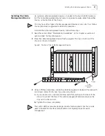
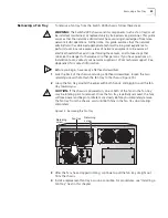
Figure 6 Installing a Clip Nut on the Rack
5
Have two people lift the chassis through the front of the rack, until both flanges
on the chassis are flush against the front of the rack.
NOTE:
You may require additional people to help balance the chassis or secure it
to the rack with screws.
6
Using the pre-installed flange pins for guidance, match the slots on the flange to
the marked area of the rack or to the clip nuts that you positioned on the rack.
Continue to support the back of the chassis.
7
Secure the chassis to the rack with four 10-32 inch screws (and clip nuts if
applicable):
a
Install one screw in the bottom part of each flange.
b
Install one screw in the top part of each flange.
WARNING:
Continue to support the chassis until you have securely installed all
four screws (two screws per flange). If you release the weight of the chassis on
fewer than four fully inserted screws, the chassis may drop off the rack. Personal
injury or serious damage to the chassis may result.
c
Tighten all screws completely.
NOTE:
Tighten the screws that attach the chassis to the rack to a Torque
Specification of 22-25 in/lb (inch-pounds).
8
Ensure that the front, sides, and the rear of the chassis are unobstructed and that
they are in compliance with ventilation requirements.
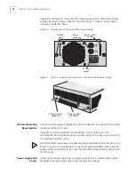
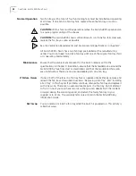
10-32 inch screw
Rack rail
Be sure to thread the screw
through this nut to securely
attach each clip to the rack
Top view
Summary of Contents for 4005
Page 28: ...28 CHAPTER 4 SWITCH 4005 CHASSIS ...
Page 36: ...36 CHAPTER 5 SWITCH 4005 POWER SUPPLIES ...
Page 76: ...76 GLOSSARY ...


