30
C
HAPTER
5: S
WITCH
4005 P
OWER
S
UPPLIES
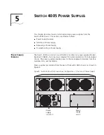
Figure 10 and Figure 11 show the front and rear views of a Switch 4005 power
supply. The power supply connector shown in Figure 11 makes contact with a
connector inside the chassis.
Figure 10 External View of the Switch 4005 Power Supply
Figure 11 Chassis Connector and Guide Pins on the Switch 4005 Power Supply
Normal Operating
Requirements
Only one power supply is required for normal operation of a chassis that contains
modules and fans in all slots.
However, to help to maintain high availability of your network, 3Com
recommends that you install a second power supply in the chassis and connect it
to a dedicated power source.
All Switch 4005 chassis have one power supply preinstalled at the manufacturing
center. If you want to configure your chassis for high availability, order a second
power supply and install it at your site. Save the blank faceplate that you remove
for future use.
Power Supply Slot
Covers
If one of the power supply slots is empty, ensure that it is covered with a blank
faceplate to ensure proper airflow and cooling of the chassis.
Retainer
screw
AC input
socket
Power
indicators
Power supply
handle
Power supply
connector
Power supply
guide pin
Summary of Contents for 4005
Page 28: ...28 CHAPTER 4 SWITCH 4005 CHASSIS ...
Page 36: ...36 CHAPTER 5 SWITCH 4005 POWER SUPPLIES ...
Page 76: ...76 GLOSSARY ...


