6
S
WITCH
4005 F
AN
T
RAYS
This chapter describes how to remove and install a fan tray (Model Number
3C16823) from the Switch 4005 chassis. The main sections are titled as follows:
■
Fan Tray Description
■
Removing a Fan Tray
■
Installing a Fan Tray
■
Troubleshooting a Fan Tray
Fan Tray Description
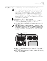
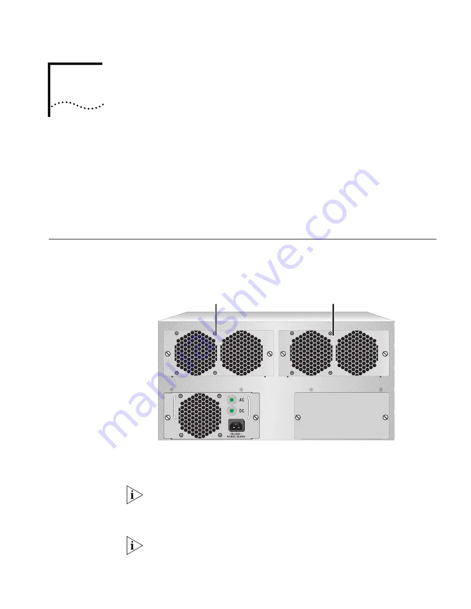
The Switch 4005 chassis can contain two fan trays (Model Number 3C16823),
which are installed from the rear of the chassis, as shown in Figure 14.
Figure 14 Fan Trays in the Switch 4005 Chassis
Heat is produced while the Switch 4005 is operating. To cool the chassis, the fan
trays pull in cooler ambient air from vents in the module faceplates and then expel
the hot air through vents in the rear of the fan trays.
The power supplies also contain small fans. Their fans pull air from side vents in
the chassis and expel hot air through vents in the rear of the power supplies.
Fan tray failure or ambient air that is too hot will eventually cause the Switch 4005
to power off. Ensure that your site meets the requirements described in Chapter 3.
The chassis does not contain temperature sensors. However, a trap is sent to the
management application when one or more fans in a fan tray is not operating
normally.
Fan tray
(in slot 2)
Fan tray
(in slot 1)
Summary of Contents for 4005
Page 28: ...28 CHAPTER 4 SWITCH 4005 CHASSIS ...
Page 36: ...36 CHAPTER 5 SWITCH 4005 POWER SUPPLIES ...
Page 76: ...76 GLOSSARY ...

