38
C
HAPTER
6: S
WITCH
4005 F
AN
T
RAYS
Normal Operation
Two fan trays with a total of four functioning fans must be installed and operating
at all times. If one fan in a fan tray fails, replace the entire fan tray as soon as
possible.
CAUTION:
All four fans must be operational when the Switch 4005 is powered on
to ensure proper cooling of the chassis.
CAUTION:
The
Switch 4005 chassis will continue to run if one fan fails. However,
replace the fan tray as soon as possible.
See the Ventilation Requirements and Environmental Specifications in Chapter 3.
All Switch 4005 chassis have two fan trays preinstalled at the manufacturing
center. You do not need to install a fan tray until one of the original fan trays fails
or is operating intermittently.
Maintenance
Ensure that the ambient environment for the Switch remains within the
specifications in Chapter 3. In addition, ensure that the immediate area around the
Switch 4005 is free from dust or small debris and that the module and fan vents
are unobstructed. There are no user-serviceable parts on a fan tray.
If Failure Occurs
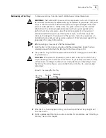
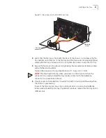
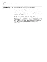
If one or both of the fans in a fan tray fails or operates intermittently, remove and
reinsert the fan tray as described in sections “Removing a Fan Tray” and “Installing
a Fan Tray” in this chapter. If problems continue, remove the fan tray and replace it
with a new one. There are no user-serviceable parts in a fan tray. Do not attempt
to fix it. Consult your purchase records so that you can determine if the incident
occurred during the warranty period, and return the faulty fan tray to your
supplier or to 3Com. The warranty terms are printed in the
Switch 4005 Key
Information Guide
.
Hot Swap
You can remove or install a fan tray while the Switch is powered on. This activity is
called
hot swap
.
Summary of Contents for 4005
Page 28: ...28 CHAPTER 4 SWITCH 4005 CHASSIS ...
Page 36: ...36 CHAPTER 5 SWITCH 4005 POWER SUPPLIES ...
Page 76: ...76 GLOSSARY ...


