46
C
HAPTER
7: S
WITCH
F
ABRIC
M
ANAGEMENT
M
ODULES
AND
I
NTERFACE
M
ODULES
■
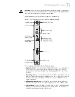
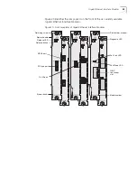
General status LEDs
— These are the Diagnostics (D), Power (PWR),
Primary (P), and Release (R) LEDs. Table 5 explains their purposes.
■
Mode button
and LEDs
— You use this button on the SFMM to set the Port
Mode LED display on all interface modules to one of three modes: Activity, Full
Duplex, or Flow Control. Table 6 defines each mode. You cannot have different
modes display on different modules.
■
Model Number
— Use this number to order another SFMM from your 3Com
supplier or to reference problems that you describe to technical support
personnel.
■
Console port
— Use this shielded male DB-9 connector to make a RS-232
serial connection from a terminal or PC with terminal emulation software and a
standard null modem cable to access the CLI. Table 7 lists the console port
pinouts.
Table 5
Definitions of General Status LEDs
LED Name
Condition
Description
Diag
(Diagnostics)
Flashing green
Green
Self-diagnostic process or software download is
occurring.
System has passed diagnostics or completed
software download.
Power
Off
Green
Module is not receiving power.
Module is receiving power.
Primary
Off
Blue
Module is in Standby mode.*
Module is in Primary mode and is functioning as the
central backplane aggregator and management
entity for the Switch 4005.
Release
Flashing amber
Amber
System is preparing for module removal.
Module is ready for removal.
Table 6
Definitions of Mode LEDs on the Switch Fabric Management Module
LED Name
Condition
Description
ACT*
(Activity)
Green
Off
Port Mode LEDs on all interface modules display
network activity.
One of the other two modes is selected.
FDX*
(Full Duplex)
Green
Off
Port Mode LEDs on all interface modules display
full-duplex status.
One of the other two modes is selected.
FC*
(Flow Control)
Green
Off
Port Mode LEDs on all interface modules display
flow-control status.
One of the other two modes is selected.
* Use the Mode button on the primary SFMM to change the Port Mode LED display selection, which
applies to all ports on all interface modules.
Summary of Contents for 4005
Page 28: ...28 CHAPTER 4 SWITCH 4005 CHASSIS ...
Page 36: ...36 CHAPTER 5 SWITCH 4005 POWER SUPPLIES ...
Page 76: ...76 GLOSSARY ...


