Interface Module Overview
49
Interface Module
Overview
The Switch 4005 contains fourteen slots in total, with twelve of those slots being
designated for interface modules. Fast Ethernet and Gigabit Interface Modules can
occupy any of the slots that are numbered 1 – 12 and can be installed in any order.
They cannot occupy slots M1 and M2, which are designated for Switch Fabric
Management Modules.
Feature Configuration
Process
To configure features that affect ports on an interface module, you connect to
either the Web or CLI management interface on the primary Switch Fabric
Management Module. You do not connect to interface modules separately. In
addition, you do not load software on interface modules.
Traffic Handling
Each interface module learns addresses of locally attached devices and maintains a
database. When the source port and destination port of a given packet are located
on the same interface module, the packet remains local to the interface module
and is switched or routed between these ports.
However, when the destination address of a given packet is not local, the interface
module sends the packet over the backplane to the primary Switch Fabric
Management Module, which switches or routes the packet to the proper module
or floods it.
Hot Swap
All Fast Ethernet and Gigabit Ethernet Interface Modules support hot swapping,
which means that you can remove modules and install modules while the chassis
is powered up and operating. Hot swapping does not interfere with the general
operation of the Switch. However, see the caveats and cautions in the “Safety
Precautions” and “Handling Precautions” sections.
Fast Ethernet Interface
Modules
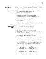
3Com offers two Fast Ethernet modules to suit different cabling infrastructures.
This section outlines the physical attributes of each module.
8-port 10/100BASE-TX
Fast Ethernet Module
■
Model Number — 3C16828
■
Size — Occupies one slot in the Switch 4005 chassis
■
Functionality — Layer 2 and Layer 3 switching
■
Physical features:
■
Diagnostic LED shows module status.
■
Release button and LED are used to remove the module.
■
Eight 10/100BASE-TX shielded RJ-45 ports provide a 10 Mbps or 100 Mbps
connection. Ports auto-negotiate for connection speed, duplex mode, and
flow control.
■
Module and Port LEDs — See Table 11 on page 52 for definitions.
■
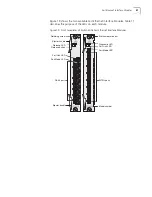
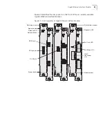
Front faceplate — See Figure 19 on page 51 for details.
■
Cabling requirements:
■
Category 5 UTP or STP.
■
Maximum Segment Length for half or full duplex is 100 m (328 ft).
■
All RJ-45 ports on the module have automatic MDI/MDI-X detection.
Summary of Contents for 4005
Page 28: ...28 CHAPTER 4 SWITCH 4005 CHASSIS ...
Page 36: ...36 CHAPTER 5 SWITCH 4005 POWER SUPPLIES ...
Page 76: ...76 GLOSSARY ...


