56
C
HAPTER
7: S
WITCH
F
ABRIC
M
ANAGEMENT
M
ODULES
AND
I
NTERFACE
M
ODULES
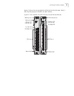
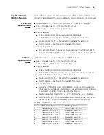
Table 13 lists and explains the status LEDs on Gigabit Ethernet Interface Modules
and explains their modes.
Table 13
LED Indicators on Gigabit Ethernet Interface Modules
LED
State or Color
Definition
Diag
(Diagnostics)
Green
Power is on (normal operation).
Flashing Green
Diagnostics is in progress.
Off
After initial insertion or module reset, the LED
remains unlit for approximately 3 seconds. At other
times, an unlit LED indicates diagnostic failure.
Release
Amber
Module is ready for removal.
Flashing Amber
System is preparing for module removal.
Off
Module is operating in its normal state.
Link
Amber
Port is operating at 10 Mbps
1
.
Green
Port is operating at 100 Mbps
1
.
Flashing Green
Port is operating at 1000 Mbps.
Flashing Amber
Port is set to disabled.
Off
Cable is not connected or link is down.
Mode
2
If this LED is Amber
and FC LED on SFMM
is Green
Flow control is enabled.
If this LED is Off and
FC LED on SFMM is
Green
Flow control is disabled.
If this LED is Amber
and FDX LED on
SFMM is Green
Port is operating at full duplex.
If this LED is Off and
FDX LED on SFMM is
Green
Port is operating at half duplex
3
.
If this LED is Amber
and Act LED on
SFMM is Green
Port is receiving or transmitting packets.
If this LED is Off and
Act LED on SFMM is
Green
Port is not active.
1
10 Mbps and 100 Mbps operation are possible with the 1000BASE-T module only (not with
GBIC or 1000BASE-SX modules).
2
Use the Mode button on the Switch Fabric Management Module (SFMM) to select the
display mode, which applies to all interface modules. To determine the mode that is selected
when you view a Port Mode LED on an interface module, look at the Port Mode LED on the
SFMM.
3
Half duplex transmission is possible with the GBIC and 1000BASE-T modules only (not with
the 1000BASE-SX module).
Summary of Contents for 4005
Page 28: ...28 CHAPTER 4 SWITCH 4005 CHASSIS ...
Page 36: ...36 CHAPTER 5 SWITCH 4005 POWER SUPPLIES ...
Page 76: ...76 GLOSSARY ...


