58
C
HAPTER
7: S
WITCH
F
ABRIC
M
ANAGEMENT
M
ODULES
AND
I
NTERFACE
M
ODULES
ESD Safety Information
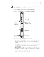
Electrostatic discharge (ESD) can damage components of the module. ESD, which
occurs when the module is improperly handled, can cause complete or
intermittent failures.
CAUTION:
To prevent ESD-related damage:
■
Always wear an ESD wrist strap (not provided) when you handle a module,
ensuring that the strap makes good skin contact and is properly grounded.
■
Keep the module in its antistatic bag until you are ready to install it.
Handling Precautions
When you handle the module, follow these precautions:
■
Always handle the module by the front panel only.
■
Do not touch the components, pins, leads, or solder connections.
■
Before you push the module into the chassis, make sure that the module
ejector handles are open.
■
Do not twist or otherwise force the module into the chassis when you insert it.
Use the upper and lower module guides to slowly and carefully slide the
module into the chassis.
■
Keep the module in its antistatic bag until you are ready to install it.
Installation Prerequisites
Before you install a module, make the following preparations:
■
Verify that the chassis is properly installed in a rack, on a table, or on a shelf,
according to the instructions in Chapter 4.
■
Have a flat-blade torque screwdriver available to secure the module to the
chassis after you install it.
■
Read the
Switch 4005 Release Notes
for potential important information about
installing and upgrading modules in an existing chassis or a new chassis.
Release notes are not included with the product packaging. You must
download a copy of the release notes from the 3Com Web site. Begin by
clicking the “Downloads” link on this page:
http://support.3com.com/index.htm
Slot Restrictions
■
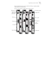
Install a Switch Fabric Management Module (SFMM) in a slot that is labeled M1
or M2.
■
Install Fast Ethernet or Gigabit Ethernet Interface Modules in slots that are
labeled 1 through 12.
■
For proper airflow and cooling in the chassis, ensure that blank faceplates cover
any empty module slots.
Summary of Contents for 4005
Page 28: ...28 CHAPTER 4 SWITCH 4005 CHASSIS ...
Page 36: ...36 CHAPTER 5 SWITCH 4005 POWER SUPPLIES ...
Page 76: ...76 GLOSSARY ...


