110
C
HAPTER
19: L
OGGING
IN
THROUGH
T
ELNET
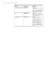
Figure 34
Launch Telnet
4
Enter the password when the Telnet window displays “Login authentication” and
prompts for login password. The CLI prompt (such as <S4200G>) appears if the
password is correct. If all VTY user interfaces of the switch are in use, you will fail to
establish the connection and receive the message that says “All user interfaces are
used, please try later!”. A S4200G series Ethernet switch can accommodate up to five
Telnet connections at same time.
5
After successfully Telneting to a switch, you can configure the switch or display the
information about the switch by executing corresponding commands. You can also
type ? at any time for help.
A Telnet connection will be terminated if you delete or modify the IP address of the
VLAN interface in the Telnet session.
By default, commands of level 0 are available to Telnet users authenticated by
password. Refer to “Command Level/Command View” in Chapter 1 for information
about command hierarchy.
Telneting to Another
Switch from the Current
Switch
You can Telnet to another switch from the current switch. In this case, the current
switch operates as the client, and the other operates as the server. If the
interconnected Ethernet ports of the two switches are in the same LAN segment,
make sure the IP addresses of the two management VLAN interfaces to which the
two Ethernet ports belong to are of the same network segment, or the route
between the two VLAN interfaces is available.
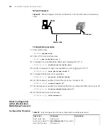
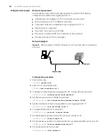
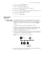
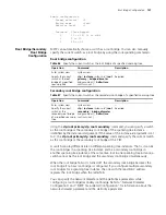
As shown in Figure 35, after Telneting to a switch (labeled as Telnet client), you can
Telnet to another switch (labeled as Telnet server) by executing the
telnet
command
and then to configure the later.
Figure 35
Network diagram for Telneting to another switch from the current switch
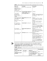
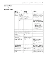
1
Configure the user name and password for Telnet on the switch operating as the
Telnet server. Refer to “Telnet Configuration with Authentication Mode Being None”,
“Telnet Configuration with Authentication Mode Being Password”, and “Telnet
Configuration with Authentication Mode Being Scheme” for more.
2
Telnet to the switch operating as the Telnet client.
3
Execute the following command on the switch operating as the Telnet client:
<S4200G>
telnet xxxx
Telnet client
PC
Telnet server
Telnet client
PC
Telnet server
Summary of Contents for 4200G 12-Port
Page 10: ...8 CONTENTS...
Page 14: ...4 ABOUT THIS GUIDE...
Page 46: ...32 CHAPTER 5 LOGGING IN THROUGH WEB BASED NETWORK MANAGEMENT SYSTEM...
Page 48: ...34 CHAPTER 6 LOGGING IN THROUGH NMS...
Page 60: ...46 CHAPTER 9 VLAN CONFIGURATION...
Page 64: ...50 CHAPTER 10 MANAGEMENT VLAN CONFIGURATION...
Page 80: ...66 CHAPTER 13 GVRP CONFIGURATION...
Page 98: ...84 CHAPTER 15 LINK AGGREGATION CONFIGURATION...
Page 112: ...98 CHAPTER 18 MAC ADDRESS TABLE MANAGEMENT...
Page 126: ...112 CHAPTER 19 LOGGING IN THROUGH TELNET...
Page 162: ...148 CHAPTER 20 MSTP CONFIGURATION...
Page 274: ...260 CHAPTER 29 IGMP SNOOPING CONFIGURATION...
Page 276: ...262 CHAPTER 30 ROUTING PORT JOIN TO MULTICAST GROUP CONFIGURATION...
Page 298: ...284 CHAPTER 33 SNMP CONFIGURATION...
Page 304: ...290 CHAPTER 34 RMON CONFIGURATION...
Page 338: ...324 CHAPTER 36 SSH TERMINAL SERVICES...
Page 356: ...342 CHAPTER 38 FTP AND TFTP CONFIGURATION...
Page 365: ...Information Center Configuration Example 351 S4200G terminal logging...
Page 366: ...352 CHAPTER 39 INFORMATION CENTER...
Page 378: ...364 CHAPTER 40 BOOTROM AND HOST SOFTWARE LOADING...
Page 384: ...370 CHAPTER 41 Basic System Configuration and Debugging...
Page 388: ...374 CHAPTER 43 NETWORK CONNECTIVITY TEST...
Page 406: ...392 CHAPTER 45 CONFIGURATION OF NEWLY ADDED CLUSTER FUNCTIONS...


