Introduction to 802.1x
153
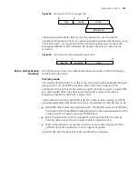
Figure 48
The format of an EAP-message field
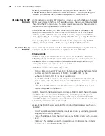
The Message-authenticator field, as shown in Figure 49, is used to prevent
unauthorized interception of access requesting packets during authentications using
CHAP, EAP, and so on. A packet with the EAP-message field must also have the
Message-authenticator field, otherwise the packet is regarded as invalid and is
discarded.
Figure 49
The format of an Message-authenticator field
802.1x Authentication
Procedure
An S4200G series switch can authenticate supplicant systems in EAP terminating
mode or EAP relay mode.
EAP relay mode
This mode is defined in 802.1x. In this mode, EAP-packets are encapsulated in higher
level protocol (such as EAPoR) packets to allow them successfully reach the
authentication server. This mode normally requires the RADIUS server to support the
two newly-added fields: the EAP-message field (with a value of 79) and the
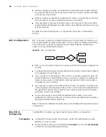
Message-authenticator field (with a value of 80).
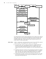
Three authentication ways, EAP-MD5, EAP-TLS (transport layer security), and PEAP
(protected extensible authentication protocol), are available for the EAP relay mode.
■
EAP-MD5 authenticates the supplicant system. The RADIUS server sends MD5 keys
(contained in EAP-request/MD5 challenge packets) to the supplicant system, which
in turn encrypts the passwords using the MD5 keys.
■
EAP-TLS authenticates both the supplicant system and the RADIUS server by
checking their security licenses to prevent data from being stolen.
■
PEAP creates and uses TLS security channels to ensure data integrity and then
performs new EAP negotiations to verify supplicant systems.
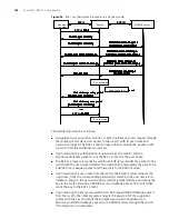
Figure 50 describes the basic EAP-MD5 authentication procedure.
Type
Length
String
0
1
2
EAP packet
Type
Length
String
0
1
2
EAP packet
type=80
length=18
string...
0
1
2
17
Summary of Contents for 4200G 12-Port
Page 10: ...8 CONTENTS...
Page 14: ...4 ABOUT THIS GUIDE...
Page 46: ...32 CHAPTER 5 LOGGING IN THROUGH WEB BASED NETWORK MANAGEMENT SYSTEM...
Page 48: ...34 CHAPTER 6 LOGGING IN THROUGH NMS...
Page 60: ...46 CHAPTER 9 VLAN CONFIGURATION...
Page 64: ...50 CHAPTER 10 MANAGEMENT VLAN CONFIGURATION...
Page 80: ...66 CHAPTER 13 GVRP CONFIGURATION...
Page 98: ...84 CHAPTER 15 LINK AGGREGATION CONFIGURATION...
Page 112: ...98 CHAPTER 18 MAC ADDRESS TABLE MANAGEMENT...
Page 126: ...112 CHAPTER 19 LOGGING IN THROUGH TELNET...
Page 162: ...148 CHAPTER 20 MSTP CONFIGURATION...
Page 274: ...260 CHAPTER 29 IGMP SNOOPING CONFIGURATION...
Page 276: ...262 CHAPTER 30 ROUTING PORT JOIN TO MULTICAST GROUP CONFIGURATION...
Page 298: ...284 CHAPTER 33 SNMP CONFIGURATION...
Page 304: ...290 CHAPTER 34 RMON CONFIGURATION...
Page 338: ...324 CHAPTER 36 SSH TERMINAL SERVICES...
Page 356: ...342 CHAPTER 38 FTP AND TFTP CONFIGURATION...
Page 365: ...Information Center Configuration Example 351 S4200G terminal logging...
Page 366: ...352 CHAPTER 39 INFORMATION CENTER...
Page 378: ...364 CHAPTER 40 BOOTROM AND HOST SOFTWARE LOADING...
Page 384: ...370 CHAPTER 41 Basic System Configuration and Debugging...
Page 388: ...374 CHAPTER 43 NETWORK CONNECTIVITY TEST...
Page 406: ...392 CHAPTER 45 CONFIGURATION OF NEWLY ADDED CLUSTER FUNCTIONS...


