10
M
ANAGEMENT
VLAN C
ONFIGURATION
Introduction to
Management VLAN
Management VLAN
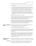
To manage an Ethernet switch remotely through Telnet or network management, the
switch need to be assigned an IP address. As for a S4200G series Layer 2 Ethernet
switch, only the management VLAN interface can be assigned an IP address.
You can assign an IP address to a management VLAN interface in one of the following
three ways:
■
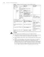
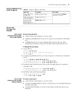
Using commands to assign IP addresses
■
Through BOOTP (In this case, the switch operates as a BOOTP client.)
■
Through dynamic host configuration protocol (DHCP) (In this case, the switch
operates as a DHCP client)
The three above mentioned ways are mutually exclusive. That is, the IP address
obtained in a new way overwrites the one obtained in the previously configured way
and the overwritten IP address is then released. For example, if you assign an IP
address to a VLAN interface by using the corresponding commands and then apply
for another IP address through BOOTP (using the
ip address bootp-alloc
command),
the former IP address will be removed, and the final IP address of the VLAN interface
is the one obtained through BOOTP.
Static Route
A static route is configured manually by an administrator. You can make a network
with relatively simple topology to operate properly by simply configuring static routes
for it. Configuring and using static routes wisely helps to improve network
performance and can guarantee bandwidth for important applications.
The disadvantages of static route lie in that: When a fault occurs or the network
topology changes, static routes may become unreachable, which in turn results in
network failures. In this case, manual configurations are needed to recover the
network.
To access a 4200G 24-Port series Ethernet switch through networks, you can
configure static routes for it.
Management VLAN
Configuration
Prerequisites
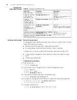
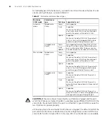
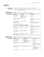
Before configuring the management VLAN, make sure the VLAN operating as the
management VLAN exists. If VLAN 1 (the default VLAN) is the management VLAN,
just go ahead.
Summary of Contents for 4200G 12-Port
Page 10: ...8 CONTENTS...
Page 14: ...4 ABOUT THIS GUIDE...
Page 46: ...32 CHAPTER 5 LOGGING IN THROUGH WEB BASED NETWORK MANAGEMENT SYSTEM...
Page 48: ...34 CHAPTER 6 LOGGING IN THROUGH NMS...
Page 60: ...46 CHAPTER 9 VLAN CONFIGURATION...
Page 64: ...50 CHAPTER 10 MANAGEMENT VLAN CONFIGURATION...
Page 80: ...66 CHAPTER 13 GVRP CONFIGURATION...
Page 98: ...84 CHAPTER 15 LINK AGGREGATION CONFIGURATION...
Page 112: ...98 CHAPTER 18 MAC ADDRESS TABLE MANAGEMENT...
Page 126: ...112 CHAPTER 19 LOGGING IN THROUGH TELNET...
Page 162: ...148 CHAPTER 20 MSTP CONFIGURATION...
Page 274: ...260 CHAPTER 29 IGMP SNOOPING CONFIGURATION...
Page 276: ...262 CHAPTER 30 ROUTING PORT JOIN TO MULTICAST GROUP CONFIGURATION...
Page 298: ...284 CHAPTER 33 SNMP CONFIGURATION...
Page 304: ...290 CHAPTER 34 RMON CONFIGURATION...
Page 338: ...324 CHAPTER 36 SSH TERMINAL SERVICES...
Page 356: ...342 CHAPTER 38 FTP AND TFTP CONFIGURATION...
Page 365: ...Information Center Configuration Example 351 S4200G terminal logging...
Page 366: ...352 CHAPTER 39 INFORMATION CENTER...
Page 378: ...364 CHAPTER 40 BOOTROM AND HOST SOFTWARE LOADING...
Page 384: ...370 CHAPTER 41 Basic System Configuration and Debugging...
Page 388: ...374 CHAPTER 43 NETWORK CONNECTIVITY TEST...
Page 406: ...392 CHAPTER 45 CONFIGURATION OF NEWLY ADDED CLUSTER FUNCTIONS...

