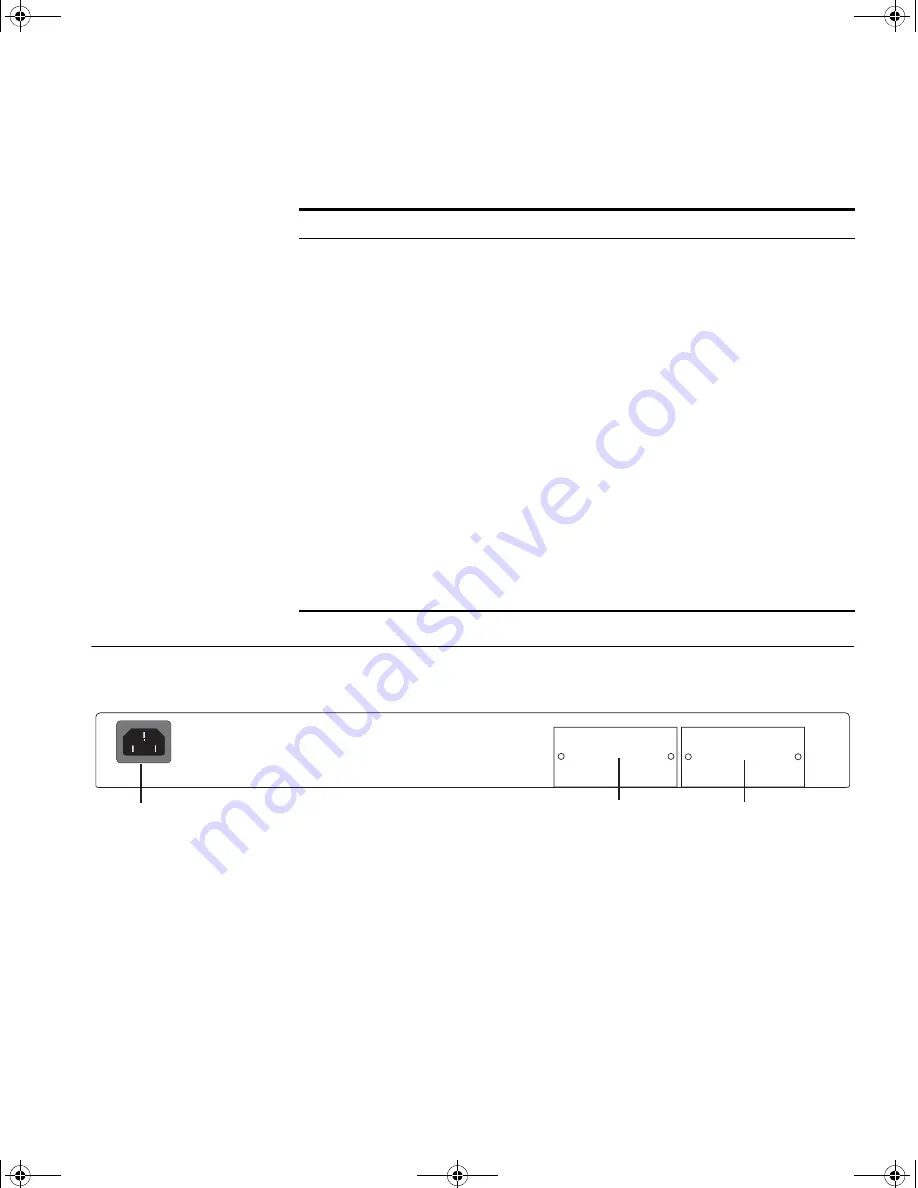
Switch 4200G — Rear View Detail
19
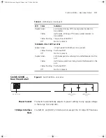
Switch 4200G —
Rear View Detail
Figure 4
Switch 4200G—rear view
Power Socket
The Switch automatically adjusts its power setting to any supply voltage
in the range 100–240 VAC.
10 Gbps Interface
Slots
The MOD 1 and MOD 2 interface slots accept the 10 Gbps SFP modules.
Duplex Green
Full duplex, blinking off for every packet received or
transmitted.
Yellow
Half duplex, blinking off for every packet received or
transmitted.
Yellow flashing
The port has failed POST.
Off
No link is present.
1000BASE-X Port SFP Port LEDs
Speed Green
A high speed (1000 Mbps) link is present.
Yellow Flashing
Port failed POST.
Off
No link is present.
Duplex Green
Full duplex packets are being transmitted/received on the
port.
Yellow
Half duplex packets are being transmitted/received on the
port.
Yellow flashing
Port failed POST.
Off
No link is present.
Table 5
LED Behavior (continued)
LED
Color
Indicates
A
C
Power Input
MOD 1
MOD 2
10G
b
ps Interf
ac
e
Slot 1
10G
b
ps Interf
ac
e
Slot 2
10014914AA.book Page 19 Friday, July 7, 2006 2:08 PM
Summary of Contents for 4200G PWR
Page 4: ...10014914AA book Page 4 Friday July 7 2006 2 08 PM ...
Page 30: ...30 CHAPTER 2 INSTALLING THE SWITCH 10014914AA book Page 30 Friday July 7 2006 2 08 PM ...
Page 74: ...74 CHAPTER 5 UPGRADING SOFTWARE 10014914AA book Page 74 Friday July 7 2006 2 08 PM ...
Page 92: ...92 APPENDIX B PIN OUTS 10014914AA book Page 92 Friday July 7 2006 2 08 PM ...
Page 96: ...96 APPENDIX C TECHNICAL SPECIFICATIONS 10014914AA book Page 96 Friday July 7 2006 2 08 PM ...
Page 104: ...10014914AA book Page 104 Friday July 7 2006 2 08 PM ...


