62
C
HAPTER
6: C
ONFIGURING
THE
C
ORE
B
UILDER
7000 F
AMILY
ATM S
WITCH
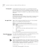
PNNI Parameter Section
If PNNI was selected as the routing mode, in
this section you are prompted to enter the PNNI node level, i.e., the
hierarchy level of the peer group to which it the node belongs. Enter a
value in the range 0 to 104.
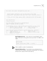
LE Parameters Section
In this section you are prompted to enable or
disable the resident LECS and LES of the switch. Enter values as follows:
1
At the “Resident LECS state” prompt, enter
1
to enable the resident LECS
or enter
0
to disable the resident LECS.
If you enter 1, the resident LES will be enabled automatically and no
further prompt will be displayed. If you enter 0, the “LES state” prompt
will be displayed.
2
At the “LES state” prompt, enter
1
to enable the resident LES or enter
0
to disable the resident LES.
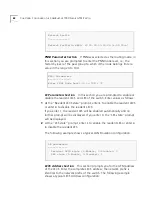
The following example shows a typical LAN Emulation configuration.
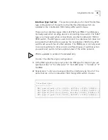
LECS Address Section
This section prompts you for the ATM address
of the LECS. Enter the complete LECS address; the network prefix is
identical to the network prefix of the switch. The following example
shows a typical LECS Address configuration:
Network Prefix
=
-------------
Network Prefix(In HEX): 47.00.00.00.00.00.3c.00.00.a*
PNNI Parameters
=--------------
Enter PNNI Node Level [0 to 104]: 72
LE parameters
=------------
Resident LECS state (1-Enable, 0-Disable): 0
LES state (1-Enable, 0-Disable): 1
Summary of Contents for CoreBuilder 7000
Page 8: ......
Page 20: ...20 CHAPTER 1 OVERVIEW...
Page 54: ...54 CHAPTER 5 POWER ON...
Page 96: ...96 CHAPTER 8 TROUBLESHOOTING...
Page 100: ...100 APPENDIX A ATM SWITCH FA 24 CELL SWITCHING MODULE SPECIFICATIONS...
Page 104: ...104 APPENDIX B SAFETY INFORMATION...
Page 122: ...122 APPENDIX D CABLING REQUIREMENTS...
Page 128: ...128 APPENDIX E TECHNICAL SUPPORT...
Page 148: ...148 INDEX...


