ATM Switching
133
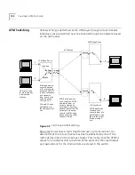
The call is transferred as follows:
1
The edge device translates the Ethernet frames into ATM cells and
forwards them to the ATM output port.
2
The ATM output port writes the VPI/VCI values for the external link for
the VC on the cell header and transmits the cells on the line that connects
the port to the switch. Cells for simultaneous calls are multiplexed on the
line.
3
The cells that are received by the switch are identified by VPI/VCI and sent
through the virtual channel internal link to the appropriate output port.
4
The output port overwrites the VPI/VCI values in the cell header with ones
for the next external link and transmits the cell over the line to the edge
device.
5
The edge device identifies the VPI/VCI values, translates the cells back into
frames, and sends them out the appropriate Ethernet port.
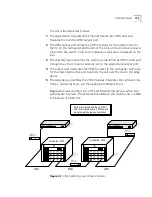
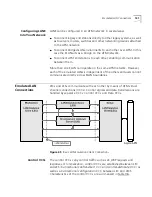
Figure 43 shows another view of the ATM switching process when two
switches are involved. The external link between the switch units is a NNI
link instead of a UNI link.
Figure 43
ATM Switching over Virtual Channel
Cells are switched and their VPI/VCI
field is translated by every ATM switch
along the path between end stations.
ETHERNET
LS2700
ATM
ETHERNET
LS2700
AT M
VPI = 6
VPI = 1
D
H
H
D
VCI = 412
VCI = 117
VPI = 3
CoreBuilder 7000
CoreBuilder 7000
H
D
VCI = 35
UNI
UNI
NNI
Summary of Contents for CoreBuilder 7000
Page 12: ......
Page 30: ...30 CHAPTER 1 ATM NETWORK BASICS...
Page 32: ...32 CHAPTER 1 ATM NETWORK BASICS...
Page 34: ...34 CHAPTER 1 ATM NETWORK BASICS Figure 8 LANE Network over WAN...
Page 96: ...96 CHAPTER 4 PRIVATE NETWORK TO NETWORK INTERFACE PNNI VERSION 1 0...
Page 184: ...184 CHAPTER 7 LAN EMULATION VERSIONS 1 0 AND 2 0...
Page 206: ...206 CHAPTER 9 DEVICE MANAGEMENT...
Page 222: ...222 APPENDIX A TECHNICAL SUPPORT...
Page 234: ...234 APPENDIX B PROTOCOLS AND INTERFACES...
Page 238: ...238 APPENDIX C COREBUILDER 7000 FAMILY ATM SWITCH SPECIFICATIONS...
Page 242: ...242 APPENDIX D SAFETY INFORMATION...

