Operation & Maintenance (OAM)
229
Operation &
Maintenance
(OAM)
The Operation and Maintenance (OAM) functions associated with the
155 Mbps UNI provide for transmission and reception of maintenance
and low level link performance monitoring between ATM devices. The
functions of the OAM are handled at the Physical Layer as well as the
ATM Layer.
The OAM works on a hand-shake basis, where a signal sent from one
end, is received and answered by the other end, resulting in an
end-to-end bi-directional flow.
Physical Layer OAM
The Physical Layer OAM information is carried in the Physical Layer
Overhead Unit together with byte and frame synchronization (F1/F3 as
part of the SONET frame). The Physical Layer OAM provides:
Maintenance signals are defined for the physical layer to indicate the
detection and location of a transmission failure.
A link transmission performance monitoring signal is defined for the
physical layer to detect and report link transmission errors. This signal
provides a low level indication of degraded link error performance.
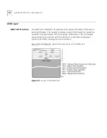
ATM Layer OAM
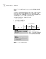
At the ATM layer, the F4-F5 flows are carried via OAM cells. The OAM cell
flow used for end-to-end management functions is carried transparently
through the private ATM switch and made available to the user. The F4
flow is used for segment or end-to-end management at the VP level. The
F5 flow is used for segment or end-to-end management at the VC level
using Payload Type (PT) code points.
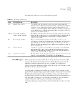
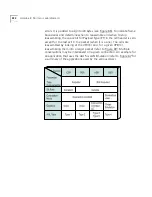
The virtual path connection (VPC) operational information is carried via
the F4 flow OAM cells. These cells have the same VPI value as the
user-data cells but are identified by pre-assigned VCI values. Two unique
VCI values are used for every VPC. The VCI value 3 is used to identify the
connection between user and network on both sides of the UNI. VCI
value 4 is used to identify the connection between user end stations.
The virtual channel connection (VCC) operation information is carried via
the F5 flow OAM cells. These cells have the same VPI/VCI values as the
user-data cells but are identified by pre-assigned code points of the PT
field. Two unique PT values are used for every VCC. PT 100 is used to
identify the connection between user and network on both sides of the
Summary of Contents for CoreBuilder 7000
Page 12: ......
Page 30: ...30 CHAPTER 1 ATM NETWORK BASICS...
Page 32: ...32 CHAPTER 1 ATM NETWORK BASICS...
Page 34: ...34 CHAPTER 1 ATM NETWORK BASICS Figure 8 LANE Network over WAN...
Page 96: ...96 CHAPTER 4 PRIVATE NETWORK TO NETWORK INTERFACE PNNI VERSION 1 0...
Page 184: ...184 CHAPTER 7 LAN EMULATION VERSIONS 1 0 AND 2 0...
Page 206: ...206 CHAPTER 9 DEVICE MANAGEMENT...
Page 222: ...222 APPENDIX A TECHNICAL SUPPORT...
Page 234: ...234 APPENDIX B PROTOCOLS AND INTERFACES...
Page 238: ...238 APPENDIX C COREBUILDER 7000 FAMILY ATM SWITCH SPECIFICATIONS...
Page 242: ...242 APPENDIX D SAFETY INFORMATION...


