62
C
HAPTER
3: E-IISP P
ROTOCOL
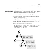
is C.2.1. A* looks at its neighbors and notices that none of them
begin with the C* prefix. The only option is to use the default port.
Since B* has the shortest network prefix which is not longer than A*
it is used as the default port. If no default port is found, a RELEASE
message is sent back to the switch that sent the SETUP message.
4
After an NNI neighbor is identified according to the procedure of the
previous step, an internal link is established to the output port to which
that neighbor is attached, and the VPI/VCI identifier and the neighbor’s
address are recorded. This completes the virtual channel up to the output
port.
5
To continue the virtual channel, a SETUP message is forwarded to the NNI
neighbor to establish an external link (connection) to it.
Hop Limit — Avoiding
Loops
One step of forwarding the SETUP message between NNI neighbors is
called a
hop
. If the number of hops exceeds a preset limit, a looping
condition is declared and a RELEASE message is returned to the sender,
terminating the process unsuccessfully with no route established.
Selecting the Hop Limit
When a network is designed using the hierarchical method of E-IISP the
hop limit is normally set to 7. For a very large network or for a network
that is not hierarchical, choose the hop limit to be the longest possible
path between two units in the network without repeating a section. To
set the hop limit, see “Update Maximum NNI Hops” on page 194 in the
Management Guide.
For information about how to display internal links and examples, see
“Display Call Routed to ATM Address” on page 165 in the Management
Guide.
Crankback
The crankback mechanism in the CoreBuilder 7000 switch automatically
re-routes a call if a virtual channel cannot be established on the path fixed
by the routing algorithm. This can happen for a number of reasons:
No route to destination
No VCC available — Number of VCCs exceed a limit
No rate available — No available bandwidth
Resources unavailable — Node internal resource problem
Summary of Contents for CoreBuilder 7000
Page 12: ......
Page 30: ...30 CHAPTER 1 ATM NETWORK BASICS...
Page 32: ...32 CHAPTER 1 ATM NETWORK BASICS...
Page 34: ...34 CHAPTER 1 ATM NETWORK BASICS Figure 8 LANE Network over WAN...
Page 96: ...96 CHAPTER 4 PRIVATE NETWORK TO NETWORK INTERFACE PNNI VERSION 1 0...
Page 184: ...184 CHAPTER 7 LAN EMULATION VERSIONS 1 0 AND 2 0...
Page 206: ...206 CHAPTER 9 DEVICE MANAGEMENT...
Page 222: ...222 APPENDIX A TECHNICAL SUPPORT...
Page 234: ...234 APPENDIX B PROTOCOLS AND INTERFACES...
Page 238: ...238 APPENDIX C COREBUILDER 7000 FAMILY ATM SWITCH SPECIFICATIONS...
Page 242: ...242 APPENDIX D SAFETY INFORMATION...

