PNNI Routing
83
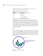
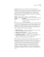
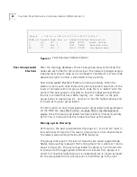
the hierarchy). Table 21 shows the updated topology database that node
A.1.2 will have after receiving this new information.
Table 21
Updated Database for Node A.1.2
Uplinks in a
Hierarchical Structure
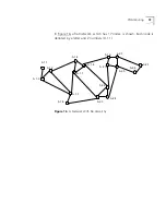
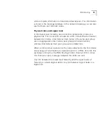
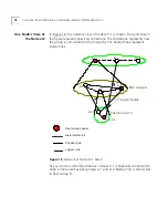
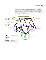
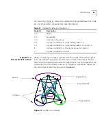
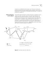
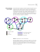
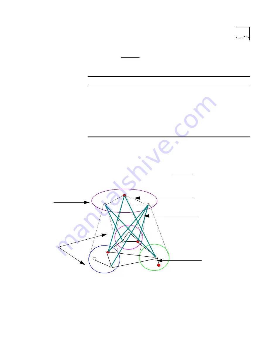
When a hierarchy is created, uplinks from the lowest level to the higher
levels are created. An uplink is a link from a node in the lower level of
hierarchy to a logical group node in a higher level. This link represents the
connection from the border node to its neighbor. Uplinks are shown for
the second level hierarchy group A in Figure 24.
Figure 24
Uplinks in a Hierarchy
Node ID
Description
A.1.2
Myself
A.1.3
My neighbor
A.1.1
A member of my group
A.2
A group connected to A.1 accessed by node A.1.2
A.3
A group connected to A.1 accessed by nodes A.1.2 and A.1.3
B
A group connected to A accessed by groups A.2 and A.3
C
A group connected to Group B
Logical Uplink
Logical Link
Physical Link
Parent
Children
Summary of Contents for CoreBuilder 7000
Page 12: ......
Page 30: ...30 CHAPTER 1 ATM NETWORK BASICS...
Page 32: ...32 CHAPTER 1 ATM NETWORK BASICS...
Page 34: ...34 CHAPTER 1 ATM NETWORK BASICS Figure 8 LANE Network over WAN...
Page 96: ...96 CHAPTER 4 PRIVATE NETWORK TO NETWORK INTERFACE PNNI VERSION 1 0...
Page 184: ...184 CHAPTER 7 LAN EMULATION VERSIONS 1 0 AND 2 0...
Page 206: ...206 CHAPTER 9 DEVICE MANAGEMENT...
Page 222: ...222 APPENDIX A TECHNICAL SUPPORT...
Page 234: ...234 APPENDIX B PROTOCOLS AND INTERFACES...
Page 238: ...238 APPENDIX C COREBUILDER 7000 FAMILY ATM SWITCH SPECIFICATIONS...
Page 242: ...242 APPENDIX D SAFETY INFORMATION...

