PNNI Signaling Protocol
95
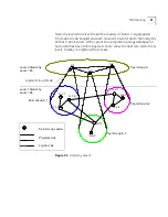
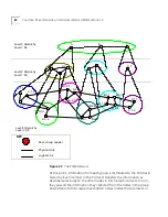
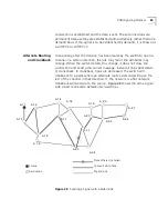
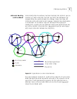
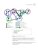
Figure 34
Alternate Routing in a Hierarchy
In this example a new DTL is generated as shown and the signal is sent.
At no point in the process is the call released. This saves time and
prevents having to crankback completely to the source, thereby saving
valuable resources.
This chapter presented PNNI in theory. Details on how to implement and
configure the PNNI network are located in Chapter 13 in the
Management Guide.
v
X
X
v
C.1.1
C.1.2
A.3.2
A.3.1
A.1.3
A.1.1
A.1.2
A.2.2
A.2.1
A.2.3
B.1.1
B.1.3
B.1.4
B.1.2
B.2.2
B.2.1
B.2.3
Peer Group Leader
Source
Destination
Chosen Path to Take
Physical Link
Signal Failure
Node to Where Signal
Cranked Back
Alternate Route
Path of Alternate Route
DTL List for this Transmission:
DTL:[A.2.2, A.2.3]
DTL:[A.2]
DTL:[A,B,C]
Summary of Contents for CoreBuilder 7000
Page 12: ......
Page 30: ...30 CHAPTER 1 ATM NETWORK BASICS...
Page 32: ...32 CHAPTER 1 ATM NETWORK BASICS...
Page 34: ...34 CHAPTER 1 ATM NETWORK BASICS Figure 8 LANE Network over WAN...
Page 96: ...96 CHAPTER 4 PRIVATE NETWORK TO NETWORK INTERFACE PNNI VERSION 1 0...
Page 184: ...184 CHAPTER 7 LAN EMULATION VERSIONS 1 0 AND 2 0...
Page 206: ...206 CHAPTER 9 DEVICE MANAGEMENT...
Page 222: ...222 APPENDIX A TECHNICAL SUPPORT...
Page 234: ...234 APPENDIX B PROTOCOLS AND INTERFACES...
Page 238: ...238 APPENDIX C COREBUILDER 7000 FAMILY ATM SWITCH SPECIFICATIONS...
Page 242: ...242 APPENDIX D SAFETY INFORMATION...

