Virtual Channels
99
External Links – ATM
Connections
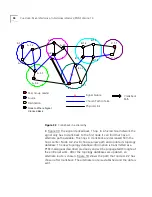
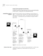
Each external link, referred to as an ATM
connection
, is uniquely
characterized by a pair of integers VPI and VCI called the
Virtual Path
Identifier
and
Virtual Channel Identifier
. The default range is VPI: 0-7; VCI:
32-511VPI: 0-2
8
; VCI: 0-2
16
.
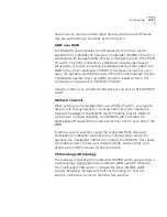
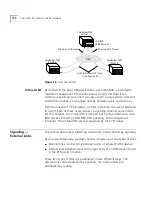
The VPI/VCI pairs are allocated by the ports at both ends of the external
link. For example, the values VPI/VCI=0/32 in link
2
were allocated by the
output port of the edge device and the input port of the ATM switch. The
fact that separate devices can allocate exactly the same VPI/VCI value is
the result of UNI signaling negotiation between them during
establishment of the virtual channel. For more information about UNI
signaling, see “Signaling — External Links” on page 104 in the
Management Guide.
Internal Link —
Switch Matrix
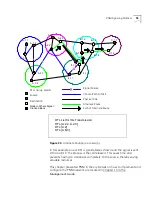
The virtual channel is completed by adding the internal link inside the
ATM devices. The internal link does not run over a fixed cable like the
external link but is rather a correspondence between the adjacent
external links which is stored in the internal memory matrix of the switch.
The ATM switch stores the correspondence
3
between link
2
and link
4
in
its internal memory matrix. Thus the VPI/VCI values of link
2
at the
specific input port of the switch are associated with the VPI/VCI values of
link
4
at the specific output port of the switch. As above, this
correspondence is established during the signaling phase.
Virtual Path —
Channel Hierarchy
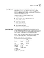
The values of VPI and VCI can be allocated independently of each other.
These two degrees of freedom allow a channel hierarchy to be
constructed. If several virtual channels with different VCI values are given
the same VPI value, then all these channels can be grouped together by
relating only to the VPI value. A virtual channel defined by its VPI only is
called a
virtual path
.
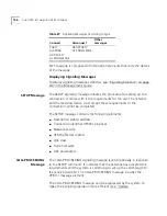
For the purposes of switching, a virtual path with a certain VPI value is as
a high-level “container” channel that carries all virtual channels with that
common VPI value; when the virtual path is switched, all the virtual
channels are also switched.
Summary of Contents for CoreBuilder 7000
Page 12: ......
Page 30: ...30 CHAPTER 1 ATM NETWORK BASICS...
Page 32: ...32 CHAPTER 1 ATM NETWORK BASICS...
Page 34: ...34 CHAPTER 1 ATM NETWORK BASICS Figure 8 LANE Network over WAN...
Page 96: ...96 CHAPTER 4 PRIVATE NETWORK TO NETWORK INTERFACE PNNI VERSION 1 0...
Page 184: ...184 CHAPTER 7 LAN EMULATION VERSIONS 1 0 AND 2 0...
Page 206: ...206 CHAPTER 9 DEVICE MANAGEMENT...
Page 222: ...222 APPENDIX A TECHNICAL SUPPORT...
Page 234: ...234 APPENDIX B PROTOCOLS AND INTERFACES...
Page 238: ...238 APPENDIX C COREBUILDER 7000 FAMILY ATM SWITCH SPECIFICATIONS...
Page 242: ...242 APPENDIX D SAFETY INFORMATION...

