56
C
HAPTER
3: G
ENERAL
T
ASKS
Managing the
Power Supply
The following command allows you to manage the power supply unit for
the CoreBuilder 7000 family ATM switch.
Display Power Supply
Info
Displays information about the power supplies installed in the
CoreBuilder 7000 family ATM switch chassis. Either one or two power
supplies may operate in the switch. When two power supplies are
installed, they work in a load-sharing mode; one takes over the whole
load in case the other fails. The screen displays the power supply slots’
occupancy and the status of the installed power supplies. The left-hand
power supply slot is designated as 1 and the right-hand slot as 2. See
“Redundant Power Supply” on page 85 in the Installation Guide for more
information about redundant power supplies.
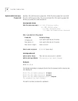
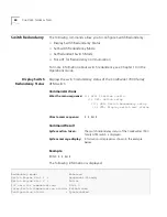
Command Actions
Command Result
Table 12 presents the possible status of the power supplies.
Example
Enter:
1 6
Information about the power supplies in the CoreBuilder 7000 family
ATM switch chassis is displayed.
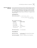
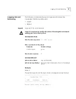
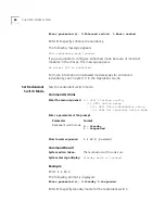
Enter the menu sequence:
(1) SYS: Platform config
(6) PWS: Power supplies
Direct access sequence:
1 6
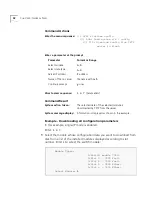
System action taken:
Information about power supplies in the CoreBuilder
switch is displayed.
System message display:
Information is displayed as shown in the example.
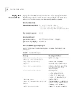
Table 12
Power Supply Status
Status
Description
OK
Power supply installed and working
Not installed
No power supply installed in this slot.
Fail
The power supply is installed but not operational
because of missing AC connection or fault.
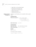
Power supply id: 1 status: OK
Power supply id: 2 status: Not installed
Summary of Contents for CoreBuilder 7000
Page 16: ......
Page 68: ...68 CHAPTER 3 GENERAL TASKS ...
Page 164: ...164 CHAPTER 6 ILMI CONFIGURATION ...
Page 462: ...462 CHAPTER 13 CONFIGURING AND MANAGING PNNI FOR THE EXTENDED VERSION ONLY ...
Page 468: ...468 APPENDIX A TECHNICAL SUPPORT ...
Page 472: ...472 APPENDIX B COREBUILDER 7000 FAMILY ATM SWITCH SPECIFICATIONS ...
Page 476: ...476 APPENDIX C SAFETY INFORMATION ...
Page 514: ...514 INDEX ...


