Switch Redundancy
67
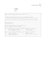
The following message appears:
Standby mode is invoked.
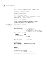
Force I/F for
Redundancy
Communication
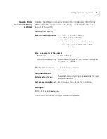
Specifies the slot number of the interface card to be used for redundancy
communication.
Command Actions
Command Result
Example
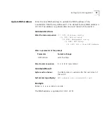
Enter:
1 1 13 4
The following prompt is displayed:
Enter parameter(s): Enter slot id(3-6)
Enter
3
to specify the slot number of the interface card to be used for
redundancy communication.
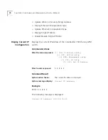
The following information is displayed:
Enter the menu sequence:
(1) SYS: Platform config
(1) SET: Switch setup
(13) SRS: Switch Redundancy setup
(4) SIR: Force I/F for red. comm.
Enter a parameter at the prompt
Parameter
Range
Slot id
3 - 6
Direct access sequence:
1 1 13 4
System action taken:
The interface card in the specified slot becomes the
card used for redundancy communication.
System message display:
The information shown in the example is displayed.
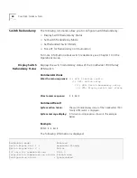
Slot id Slot status I/F card type I/F card status
------- ----------- ------------------- ---------------
-> 3 Occupied 8 port ATM I/F card Up
5 Occupied 8 port ATM I/F card Up
6 Occupied 7400 Ethernet/ATM module Up
Summary of Contents for CoreBuilder 7000
Page 16: ......
Page 68: ...68 CHAPTER 3 GENERAL TASKS ...
Page 164: ...164 CHAPTER 6 ILMI CONFIGURATION ...
Page 462: ...462 CHAPTER 13 CONFIGURING AND MANAGING PNNI FOR THE EXTENDED VERSION ONLY ...
Page 468: ...468 APPENDIX A TECHNICAL SUPPORT ...
Page 472: ...472 APPENDIX B COREBUILDER 7000 FAMILY ATM SWITCH SPECIFICATIONS ...
Page 476: ...476 APPENDIX C SAFETY INFORMATION ...
Page 514: ...514 INDEX ...


