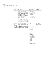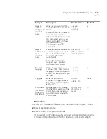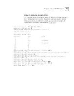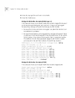
bridge vlan define (3500/9000 Layer 3)
345
bridge vlan define
✓
3500
✓
9000
9400
3900
9300
(3500/9000 Layer 3)
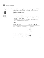
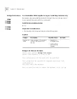
For CoreBuilder 9000: Applies to Layer 3 switching modules only.
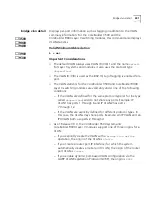
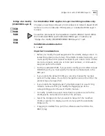
Creates a VLAN on the CoreBuilder 3500 system or a CoreBuilder 9000
Layer 3 module. When you explicitly configure a VLAN on the system, you
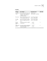
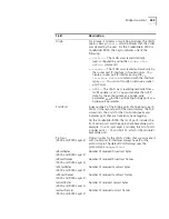
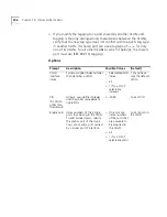
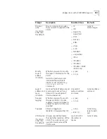
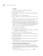
assign information such as a VLAN ID (VID), a set of bridge ports, and,
optionally, a protocol type and IEEE 802.1Q tagging.
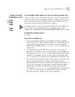
For details about this command on the SuperStack II Switch 3900, the
Switch 9300, the CoreBuilder 9400, and CoreBuilder 9000 Layer 2
modules, see “bridge vlan define (3900/9300/9400/ 9000 Layer 2)” next.
Valid Minimum Abbreviation
b v def
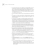
Important Considerations
■
If you have previously defined your IP VLANs with Layer 3 address
information (that is, network-based VLANs), you can redefine your IP
VLANs without Layer 3 address information. To define multiple IP
interfaces per IP VLAN, use the
ip interface define
command. (See
Chapter 16.)
■
The VLAN that you create with this command is a static VLAN. To
establish routing between static IP VLANs, define your IP VLANs and
then use the
ip interface define
command to define an IP routing
interface. As of Release 3.0, you can also specify the interface type
vlan
to create one or more IP routing interfaces for a static IP VLAN.
■
If you have a router port IP interface on the system, you
cannot
specify
the port that belongs to the router port IP interface when you
explicitly define an IP VLAN (or a VLAN that includes the IP protocol). A
router port IP interface is an alternative to static VLANs and allows
routing versus bridging. You create a router port IP interface by
entering the
ip interface define
command with the interface type
port
and a single bridge port. A router port IP interface requires
allClosed mode. See Chapter 16 for more information.
Summary of Contents for CoreBuilder 9000
Page 18: ......
Page 26: ...26 ABOUT THIS GUIDE ...
Page 27: ...I GETTING STARTED Chapter 1 Administration Overview Chapter 2 Command Summary ...
Page 28: ......
Page 64: ...64 CHAPTER 2 COMMAND SUMMARY ...
Page 65: ...II SYSTEM LEVEL FUNCTIONS Chapter 3 System Environment Chapter 4 Module Environment ...
Page 66: ......
Page 148: ......
Page 202: ......
Page 248: ...248 CHAPTER 8 FIBER DISTRIBUTED DATA INTERFACE FDDI ...
Page 250: ......
Page 320: ...320 CHAPTER 11 TRUNKS ...
Page 368: ...368 CHAPTER 14 VIRTUAL LANS VLANS ...
Page 394: ......
Page 502: ...502 CHAPTER 17 VIRTUAL ROUTER REDUNDANCY VRRP ...
Page 604: ...604 CHAPTER 19 OPEN SHORTEST PATH FIRST OSPF ...
Page 660: ...660 CHAPTER 20 IPX ...
Page 687: ...VII TRAFFIC POLICY Chapter 22 Quality of Service QoS and RSVP ...
Page 688: ......
Page 744: ...744 CHAPTER 22 QUALITY OF SERVICE QOS AND RSVP ...
Page 745: ...VIII MONITORING Chapter 23 Event Log Chapter 24 Roving Analysis ...
Page 746: ......
Page 754: ...754 CHAPTER 23 EVENT LOG ...
Page 764: ...764 CHAPTER 24 ROVING ANALYSIS ...
Page 765: ...IX REFERENCE Appendix A Technical Support ...
Page 766: ......
Page 772: ...772 APPENDIX A TECHNICAL SUPPORT ...
Page 784: ......


