758
C
HAPTER
24: R
OVING
A
NALYSIS
✓
3500
✓
9000
✓
9400
✓
3900
✓
9300
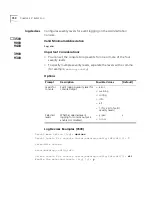
analyzer add
Defines a bridge port to serve as a dedicated analyzer port.
Valid Minimum Abbreviation
an a
Important Considerations
■
On CoreBuilder
®
3500 and CoreBuilder 9000 systems, you can
connect as many as 16 network analyzers to a system. On other
platforms, you can connect one network analyzer. For more accurate
analysis, attach the analyzer to a dedicated port instead of through a
repeater.
■
After a port is selected to serve as an analyzer port, it cannot receive
or transmit any other data. Instead, it receives only the data from the
ports to be monitored. If you have enabled the Spanning Tree Protocol
(STP) on the port, STP is automatically disabled.
■
If the physical port configuration changes in the system (that is, if you
remove or rearrange modules), the MAC address of the analyzer port
remains fixed. If you replace the module with the analyzer port with a
module of a different media type, the roving analysis port (RAP)
configuration for that port is cleared.
■
When you configure a port that is part of a virtual LAN (VLAN) as an
analyzer port, a warning is displayed because adding the port removes
the port from all VLANs. When the port is restored (when you remove
the analyzer port), it becomes a member of the default VLAN.
■
If the probe is attached to a 10 Mbps Ethernet analyzer port and the
roving analysis port (RAP) is monitoring a 100 Mbps Ethernet port
with a sustained traffic rate greater than 10 Mbps, the analyzer may
not see all of the frames.
■
After you enter a bridge port number, the system displays the MAC
address of the analyzer port. Record this information for setting up the
port that you want to monitor.
■
On the CoreBuilder 9000, the port to which the analyzer is attached
and the port you wish to monitor must be on the same blade.
■
Trunked ports and resilient link ports can not be configured as analyzer
ports.
Summary of Contents for CoreBuilder 9000
Page 18: ......
Page 26: ...26 ABOUT THIS GUIDE ...
Page 27: ...I GETTING STARTED Chapter 1 Administration Overview Chapter 2 Command Summary ...
Page 28: ......
Page 64: ...64 CHAPTER 2 COMMAND SUMMARY ...
Page 65: ...II SYSTEM LEVEL FUNCTIONS Chapter 3 System Environment Chapter 4 Module Environment ...
Page 66: ......
Page 148: ......
Page 202: ......
Page 248: ...248 CHAPTER 8 FIBER DISTRIBUTED DATA INTERFACE FDDI ...
Page 250: ......
Page 320: ...320 CHAPTER 11 TRUNKS ...
Page 368: ...368 CHAPTER 14 VIRTUAL LANS VLANS ...
Page 394: ......
Page 502: ...502 CHAPTER 17 VIRTUAL ROUTER REDUNDANCY VRRP ...
Page 604: ...604 CHAPTER 19 OPEN SHORTEST PATH FIRST OSPF ...
Page 660: ...660 CHAPTER 20 IPX ...
Page 687: ...VII TRAFFIC POLICY Chapter 22 Quality of Service QoS and RSVP ...
Page 688: ......
Page 744: ...744 CHAPTER 22 QUALITY OF SERVICE QOS AND RSVP ...
Page 745: ...VIII MONITORING Chapter 23 Event Log Chapter 24 Roving Analysis ...
Page 746: ......
Page 754: ...754 CHAPTER 23 EVENT LOG ...
Page 764: ...764 CHAPTER 24 ROVING ANALYSIS ...
Page 765: ...IX REFERENCE Appendix A Technical Support ...
Page 766: ......
Page 772: ...772 APPENDIX A TECHNICAL SUPPORT ...
Page 784: ......


