A-8
A
PPENDIX
A: S-R
EGISTERS
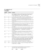
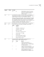
S24
150
Sets the duration, in 20-millisecond units, between pulsed DSR signals
when the Courier V.Everything modem is set to &S2 or &S3. The
default is 3 seconds.
S25
5
Sets DTR recognition time in 10-millisecond units.
S26
1
Sets duration, in 10-millisecond units, of the delay between RTS and
the CTS in synchronous mode.
S27
0
Bit-mapped register. ( See the beginning of this appendix for
information about setting bit-mapped registers).
Bit
Value
Result
0
1
Enable ITU-T V.21 modulation at 300
bps for overseas calls. In V.21 mode, the
Courier V.Everything modem answers
both Bell 103 and V.21 calls, but only
originates V.21 calls.
1
2
Enable unencoded (non- trelliscoded)
modulation in V.32 mode; this option is
part of the ITU-T V.32 recommendation,
but is rarely used.
2
4
Disable V.32 modulation; used for
testing HST modulation.
3
8
Disable 2100 Hz answer tone to allow
two V.42 devices to connect more
quickly.
4
16
See next page.
5
32
See next page.
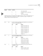
6
48
Disable V.42 Detect Phase
7
128
Unusual software incompatibility. Some
software may not accept some result
codes. This setting disables the codes
and displays the 9600 code instead. The
call's actual rate can be viewed on the
ATI6 screen.
Error control handshaking options:
Select the total value of bits 4
and 5
Bit 4
Bit 5
Result
0
0
Complete handshaking sequence: V.42
Detection, LAPM error control, MNP.
16
0
Disable MNP.
0
32
Disable V.42 Detection and LAPM.
Register
Default
Function
Summary of Contents for Courier
Page 12: ......
Page 28: ...1 14 CHAPTER 1 CONNECTING TO YOUR ISP ...
Page 36: ...3 4 CHAPTER 3 UPGRADING YOUR MODEM ...
Page 58: ...6 6 CHAPTER 6 WORKING WITH MEMORY ...
Page 64: ...8 4 CHAPTER 8 CONTROLLING EIA 232 SIGNALING ...
Page 72: ...9 8 CHAPTER 9 ACCESSING AND CONFIGURING THE COURIER V EVERYTHING MODEM REMOTELY ...
Page 80: ...10 8 CHAPTER 10 CONTROLLING DATA RATES ...
Page 96: ...12 6 CHAPTER 12 FLOW CONTROL ...
Page 108: ...13 12 CHAPTER 13 HANDSHAKING ERROR CONTROL DATA COMPRESSION AND THROUGHPUT ...
Page 112: ...14 4 CHAPTER 14 DISPLAYING QUERYING AND HELP SCREENS ...
Page 122: ...15 10 CHAPTER 15 TESTING THE CONNECTION ...
Page 142: ...17 8 CHAPTER 17 TROUBLESHOOTING ...
Page 156: ...A 14 APPENDIX A S REGISTERS ...
Page 172: ...B 16 APPENDIX B ALPHABETIC COMMAND SUMMARY ...
Page 178: ...C 6 APPENDIX C FLOW CONTROL TEMPLATE ...
Page 186: ...E 4 APPENDIX E V 25 BIS REFERENCE ...


