2-16
C
HAPTER
2: I
NSTALLATION
To connect the AUI port to a thick or thin coaxial, twisted-pair, or fiber-optic
network using a transceiver, fanout box, or hub, follow these steps:
1
Install the external transceiver, fanout box, or hub on the network.
Refer to the instructions that came with your transceiver, fanout box, or hub.
2
Connect one end of the AUI cable to the AUI port and the other end to the
transceiver, fanout box, or hub.
CAUTION:
To eliminate cable noise emission in excess of FCC Part 15 Subpart
J, or CISPR22 (EN55022) for Class A devices, all cables should be
triple-shielded (Inmac 536888 or equivalent) and have connectors with
metallic backshells. Cable shields should be connected to backshells.
3
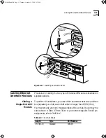
Slide the latch on the AUI port into the closed position, as shown:
30 ft (9 m)
Standard
3C6194
50 ft (15 m)
Standard
3C6195
75 ft (23 m)
Standard
3C6196
100 ft (30 m)
Standard
3C6197
150 ft (46 m)
Standard
3C6198
6 ft (2 m)
PVC
3C110-002
16 ft (5 m)
PVC
3C110-005
32 ft (10 m)
PVC
3C110- 010
49 ft (15 m)
PVC
3C110- 015
15 ft (4.6 m)
Teflon®
3C6156
30 ft (9 m)
Teflon
3C6157
50 ft (15 m)
Teflon
3C6158
75 ft (23 m)
Teflon
3C6159
15 ft (4.6 m)
Positive attachment
3C6139
30 ft (9 m)
Positive attachment
3C6140
50 ft (15 m)
Positive attachment
3C6141
75 ft (23 m)
Positive attachment
3C6142
Table 2-3
3Com AUI Cables (continued)
Length
Type
Part Number
CS3000BookFile Page 16 Tuesday, October 15, 1996 5:12 PM


