background image

Configuring Your Computer

2-1

Chapter 2
Configuring Your  Computer

This chapter explains how to configure your computer for
the 3C529 adapter.

When the computer starts, the following error
message appears:

00165-Adapter Configuration Error

The error occurs because the adapter is not in the computer’s
current configuration.  To configure your computer:

1. Make a backup copy of the PS/2 Reference Diskette.

NOTE:  If you are using a Micro Channel computer that
is not manufactured by IBM, use the corresponding
reference diskette that comes with your computer.

a.

Insert the PS/2 Reference Diskette.

b. Turn on the computer.

c.

At the main menu select Backup/Restore System
Programs.

d. Select Backup the Reference Diskette.

Follow the instructions on the screen to make the
backup of the reference diskette.

2. With the backup copy of the PS/2 Reference Diskette

still in drive A, press [Ctrl]+[Alt]+[Del] to reboot.

Summary of Contents for EtherLink 3C529

Page 1: ...16 32 Bit Micro Channel Adapters Guide For 3Com User Group Information 1 800 NET 3Com or your local 3Com office Manual Part No 09 0399 002 Published January 1994 Printed in the U S A Members of the 3Com EtherLink III family of adapters ...

Page 2: ...reproduction or disclosure is subject to restrictions set forth in subparagraph a through d of the Commercial Computer Software Restricted Rights clause at 48 C F R 52 227 19 and the limitations set forth in 3Com s standard commercial agreement for the Software Unpublished rights reserved under the copyright laws of the United States The software described in this documentation is furnished under ...

Page 3: ...form in substantial conformance to the program specifications therefor for a period of ninety 90 days from the date of purchase from 3Com or its Authorized Reseller 3Com warrants the magnetic media containing software against failure during the warranty period No updates are provided 3Com s sole obligation hereunder shall be at 3Com s discretion to refund the purchase price paid by Customer for an...

Page 4: ...ON TO ASSUME FOR IT ANY OTHER LIABILITY IN CONNECTION WITH THE SALE INSTALLATION MAINTENANCE OR USE OF ITS PRODUCTS 3COM SHALL NOT BE LIABLE UNDER THIS WARRANTY IF ITS TESTING AND EXAMINATION DISCLOSE THAT THE ALLEGED DEFECT IN THE PRODUCT DOES NOT EXIST OR WAS CAUSED BY CUSTOMER S OR ANY THIRD PERSON S MISUSE NEGLECT IMPROPER INSTALLATION OR TESTING UNAUTHORIZED ATTEMPTS TO REPAIR OR ANY OTHER CA...

Page 5: ... is no guarantee that interference will not occur in a particular installation If this equipment does cause harmful interference to radio or television reception which can be determined by turning the equipment off and on the user is encouraged to try to correct the interference by one or more of the following measures Reorient or relocate the receiving antenna Increase the separation between the ...

Page 6: ...e Berechtigung zur Überprüfung der Serie auf Einhaltung der Bestimmungen eingeräumt We hereby certify that the 3C529 3C529 TP comply with the RFI Suppression Requirements of Vfg 1046 1984 The German Postal Service was notified that the equipment is being marketed The German Postal Service has the right to re test the equipment and to verify that it complies 3Com Corporation 5400 Bayfront Plaza San...

Page 7: ...9 Adapter Drivers for a NetWare Networking Operating System NOS 9 Installing the 3C529 Adapter Drivers for a Non NetWare NOS 11 Chapter 1 Installation Unpacking the Adapter 1 1 Installing the Boot PROM 1 2 Installing the Adapter 1 2 Chapter 2 Configuring Your Computer Verifying or Changing the Computer s Configuration 2 3 Chapter 3 Changing the 3C529 Adapter Options Using the Configuration and Dia...

Page 8: ... Adapter Drivers for a Non NetWare NOS 5 6 If You Are Running Multiple Adapters 5 7 With 3 Open or LAN Manager 5 7 With NetWare 5 7 Chapter 6 Troubleshooting Running the Diagnostic Program 6 1 Starting the Group 1 Tests 6 4 Changing the Test Setup 6 6 If a Test Fails 6 8 Setting Up the Group 2 Test 6 8 Connecting a Loopback Plug 6 8 Setting Up the Group 3 Test 6 9 Setting Up an Echo Server 6 10 Ru...

Page 9: ...m A 7 Using the Command Line A 7 Command Line Keywords A 9 Appendix B Specifications Appendix C Error Messages Appendix D Technical Support On line Product Support D 1 CardBoard Bulletin Board Service D 1 3ComFacts Automated Fax Service D 2 Ask3Com On line Service D 2 3Com Documentation on CD ROM D 4 Support from Your Network Supplier D 4 U S and Canada D 4 Outside the U S and Canada D 5 Returning...

Page 10: ...onnector Pin Assignments 4 4 4 4 Connecting Twisted pair Cable 4 5 4 5 Slide Latch 4 7 4 6 Connecting the AUI Cable 4 8 4 7 Attaching the External Transceiver 4 9 5 1 Auto Installation Screen 5 3 5 2 Main Menu 5 4 6 1 Auto Installation Screen 6 3 6 2 Main Menu 6 3 6 3 Main Window with Adapter Selected 6 4 6 4 Run Tests Dialog Box 6 5 6 5 Test Setup Dialog Box 6 6 6 6 Assembling a Loopback Plug 6 9...

Page 11: ...xii Tables 3 1 Option Settings 3 5 4 1 AUI Connector Pin Assignments 4 6 A 1 Definition of Keys A 2 A 2 Definition of Menu Items A 4 A 3 Command Line Keywords A 9 ...

Page 12: ...nstructions detailing the installation of hardware and software options inside the main system unit These adapters connect your computer to an Ethernet network wired with IEEE 802 standard 10BASE 2 or 10BASE 5 coaxial cable or 10BASE T twisted pair cable This manual provides installation and diagnostic instructions for the 3C529 coax and 3C529 TP twisted pair adapters The two adapters are function...

Page 13: ...vice and support take the time to complete the product registration card Any defective 3Com adapter will be repaired or replaced at 3Com s option for as long as the adapter resides in its original IBM Personal Computer Personal System 2 or compatible computer driver software is covered by the standard 90 day limited softwarewarranty ...

Page 14: ...ue B P 609 91945 Les Ulis Cedex France Italy Greece Spain Portugal Malta 3Com Mediterraneo Srl Marketing Department Via Michelangelo Buonarroti 1 20093 Cologno Monzese MI Italy Japan 3Com Japan Marketing Department KDD Otemachi Bldg 21F 1 8 1 Otemachi Chiyoda ku Tokyo 100 Japan United Kingdom Eire 3Com UK Ltd Marketing Department Pacific House Third Avenue Globe Park Marlow on Thames Buckinghamshi...

Page 15: ...atic sensitive components on the adapter or the computer be sure to reduce any static electricity on your person One way to do that is to touch the metal chassis of your computer You can maintain grounding by wearing a wrist strap attached to the chassis 1 Carefully lift the adapter out of the box and set it aside 2 Return all packing materials to the shipping container and store the container in ...

Page 16: ...gistration Installing the Adapter WARNING The adapter board will be installed in a computer which operates with voltages that can be lethal Before you remove the cover of your computer you must observe the following steps to protect yourself and prevent damage to the system s components 1 Turn off the computer and unplug the unit from its power source 2 Disconnect all cables that are connected to ...

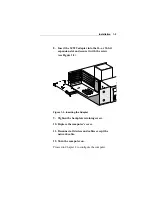
Page 17: ...ll the optional boot PROM If you are installing the boot PROM on the adapter refer to the installation instructions that accompanied the boot PROM 8 Insert the 3C529 adapter into the 16 or 32 bit expansion slot and secure it with the screw see Figure 1 3 9 Replace the computer s cover 10 Reconnect all devices and cables except the network cable ...

Page 18: ...Micro Channel computer that is not manufactured by IBM use the corresponding reference diskette that comes with your computer The procedures below may vary on other reference diskettes a Insert the PS 2 Reference Diskette b Reboot the computer c At the main menu select Backup Restore System Programs d Select Backup the Reference Diskette Follow the instructions on the screen to make the backup of ...

Page 19: ...onfiguration is complete exit the program and remove the copy of the PS 2 Reference Diskette b Reboot your computer under DOS c Go to the Quick Start section Changing 3C529 Adapter Options if you need to change software settings 5 If the ADF is not on the PS 2 Reference Diskette or if you have an external transceiver do not configure your computer automatically Continue to the next section to chan...

Page 20: ...e configuration settings use the arrow keys to select a setting and press F5 or F6 to scroll through a list of the available choices NOTE If you are using an external transceiver be sure to set Transceiver Type to external 3 To save your settings press F10 Then press Enter 4 Press F3 to return to the Set Configuration menu 5 Press F3 again to exit the program 6 Remove the copy of the PS 2 Referenc...

Page 21: ...have booted the computer under DOS 2 Place the EtherDisk diskette in the floppy drive on your computer and make that drive the current drive 3 Type at the prompt INSTALL Enter 4 The first time you use the diskette to install an adapter a license screen appears To accept the terms and conditions of the 3Com end user software license agreement type the following Y NOTE To view the full text of the l...

Page 22: ...each option that you want to change 11 Press Tab to highlight OK Press Enter 12 When the adapter is configured successfully proceed to Connecting to the Network Connecting to the Network Connect the following types of network cables to the EtherLink III adapters Cable Type Software Setting Connector Thin coaxial On board transceiver BNC Twisted pair On board transceiver RJ 45 Thick coaxial Externa...

Page 23: ...puter to the network 2 If the EtherDisk diskette is already in your floppy drive go directly to step 7 Otherwise insert the EtherDisk diskette in a floppy drive on your computer 3 Make that drive the current drive 4 Type at the prompt INSTALL Enter 5 The first time you use the diskette to install an adapter a license screen appears To accept the terms and conditions of the 3Com end user software l...

Page 24: ... with the following NLMs NetWare Loadable Modules LSLENH NLM PATCHMAN NLM MSM31X NLM ETHERTSM NLM All of the files are located on the EtherDisk diskette These files must all be copied to the same subdirectory If you are not loading them from the SYSTEM volume you must supply the DRIVEID PATH to the location of the files Type in the following commands in the order shown X can be any drive LSLENH NL...

Page 25: ... to the main menu 2 Select Network Drivers and press Enter 3 Select the appropriate driver for your network operating system and follow the instructions given in the menu NOTE All network adapters in the EtherLink III Parallel Tasking adapter family use the same drivers The drivers are backward compatible with other members of the family ...

Page 26: ...Tasking 16 32 Bit Micro Channel Adapter Guide EtherDisk diskette for the EtherLink III family of adapters CAUTION The adapter is packed in an antistatic bag to protect it during shipment To avoid damaging any highly static sensitive components on the adapter or the computer be sure to reduce any static electricity on your person One way to do that is to touch the metal chassis of your computer You...

Page 27: ...s antistatic bag until you are ready to install it NOTE After the adapter has been unpacked fill out the Product Registration Card at the back of this manual and return it to 3Com Or call 1 800 NET 3Com for immediate registration Installing the Boot PROM The boot PROM is optional and can be purchased separately If you are installing it onto the adapter follow the instructions that accompanied the ...

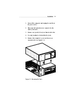
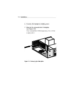
Page 28: ...wer source 2 Disconnect all cables that are connected to the main system unit 3 Remove any jewelry from your hands and wrists 4 Use only insulated or nonconductive tools 5 Remove the computer s cover and choose an expansion slot see Figure 1 1 Figure 1 1 Removing the Cover ...

Page 29: ...lation 1 4 6 Unscrew the backplate retaining screw 7 Remove the expansion slot s backplate see Figure 1 2 You can install the 3C529 adapter in any 16 or 32 bit expansion slot Figure 1 2 Removing the Backplate ...

Page 30: ... and secure it with the screw see Figure 1 3 Figure 1 3 Inserting the Adapter 9 Tighten the backplate retaining screw 10 Replace the computer s cover 11 Reconnect all devices and cables except the network cable 12 Turn the computer on Proceed to Chapter 2 to configure the computer ...

Page 31: ...ter 1 Make a backup copy of the PS 2 Reference Diskette NOTE If you are using a Micro Channel computer that is not manufactured by IBM use the corresponding reference diskette that comes with your computer a Insert the PS 2 Reference Diskette b Turn on the computer c At the main menu select Backup Restore System Programs d Select Backup the Reference Diskette Follow the instructions on the screen ...

Page 32: ...iguration options for the adapter that will allow it to function in the computer a When the automatic configuration is complete exit the program and remove the copy of the PS 2 Reference Diskette b Reboot your computer under DOS 5 If the ADF is not on the PS 2 Reference Diskette or if you have an external transceiver do not configure your computer automatically Continue to the next section to chan...

Page 33: ...he slot it is installed in Confirm that these are the configu ration settings you want If you need help press F1 If you want to change the configuration settings use the arrow keys to select a setting and press F5 or F6 to scroll through a list of the available choices NOTE If you are using an external transceiver be sure to set Transceiver Type to External 3 To save your settings press F10 Then p...

Page 34: ...ptimization or Maximum Modem Speed settings All other parameters are automatically configured by the PS 2 Reference Diskette This chapter consists of the following sections Using the Configuration and Diagnostic Program 3C529 Adapter Options Using the Configuration and Diagnostic Program You can also use the keyboard function keys or speed keys or a mouse to access the command buttons in the progr...

Page 35: ...he first time you use the diskette to install an adapter a license screen appears To accept the terms and conditions of the 3Com end user software license agreement type the following Y NOTE To view the full text of the license agreement press F1 The auto installation screen shown in Figure 3 1 appears 5 Read the screen and press Enter 6 When the main menu screen shown in Figure 3 2 appears select...

Page 36: ...Changing the 3C529 Adapter Options 3 3 Figure 3 1 Auto Installation Screen Figure 3 2 Main Menu ...

Page 37: ...ou want to configure and press Enter A screen similar to the one shown in Figure 3 3 appears showing your selection Figure 3 3 Main Window with First Adapter Selected 8 Under the Install pull down menu Configure Adapter appears already highlighted Press Enter The Adapter Configuration screen appears showing two selections Network Driver Optimization and Maximum Modem Speed Table 3 1 lists the soft...

Page 38: ... option Select a setting and press Enter 11 Press Tab to highlight OK Press Enter You must highlight OK and press Enter to save the new settings to the adapter NOTE If you want to use the same settings on other adapters you can save the configuration settings to a file Select Save under File Options in the Adapter Configuration dialog box and type in a filename For example type D CONFIG 3C529 SET ...

Page 39: ... specified For example a client may use a larger percentage of the CPU under DOS to improve network throughput On a server this may be inappropriate so the driver will attempt to minimize the CPU usage to optimize performance in a server environment Maximum Modem Speed The modem speed you choose tells the adapter how long it can disable interrupts without causing problems with the serial port The ...

Page 40: ...river changing the option setting will not make a difference NOTE The default value 9600 baud works whether you have a modem or not or even if the modem is slower than the default example 2400 baud Do not change the default option setting unless you experience problems If you experience compatibility problems between your adapter and another device in the system other than a modem selecting a high...

Page 41: ...k cables to the 3C529 adapters Cable Type Software Setting Connector Thin coaxial On board transceiver BNC Twisted pair On board transceiver RJ 45 Thick coaxial External transceiver AUI 15 pin Default setting for the 3C529 adapter Default setting for the 3C529 TP adapter NOTE To connect to the network the computer must be turned off ...

Page 42: ... 1 Adapter Backplates Connecting to the On board Transceiver Follow these steps to connect the appropriate cable to the 3C529 adapter Connecting to Thin Ethernet Cable The 3C529 adapter default setting uses the on board transceiver with thin Ethernet cable 1 Locate the adapter s BNC connector on the backplate 2 Locate a T connector on the thin Ethernet cable ...

Page 43: ...or to the adapter s BNC connector see Figure 4 2 a Align the T connector s slots with the pegs on the BNC connector b Push the T connector in and twist it clockwise until it stops BNC connector Thin Ethernet cable Figure 4 2 Connecting Thin Ethernet Cable ...

Page 44: ...isted pair cable 1 Make sure that the connector on your cable is wired appropriately for the adapter Figure 4 3 shows the RJ 45 connector pin assignments 1 2 3 4 5 6 7 8 R D T D T D R D 12345678 Figure 4 3 RJ 45 Connector Pin Assignments 2 Align the RJ 45 plug on the end of the twisted pair cable with the notch on the adapter s connector ...

Page 45: ...he hub When you first install the adapter and power up the computer the LED will be lit but the link beat is inactive For the link beat to be active enabled you need to have run the Group 3 test or have loaded the network drivers Refer to the section Link Beat LED in Chapter 6 for more information RJ 45 port RJ 45 connector Figure 4 4 Connecting Twisted pair Cable ...

Page 46: ...ure the adapter Refer to Chapter 2 Table 4 1 lists the pin assignments for the AUI attachment unit interface connector Table 4 1 AUI Connector Pin Assignments Pin Function 1 Collision shield 2 Collision 3 Transmit 4 Receive shield 5 Receive 6 Power return 7 Not used 8 Not used 9 Collision 10 Transmit 11 Transmit shield 12 Receive 13 12 volts 14 Voltage shield 15 Not used ...

Page 47: ...ting to the Network 4 7 To connect the AUI cable 1 Locate the adapter s AUI connector and move the slide latch to the open position see Figure 4 5 Closed AUI connector Slide latch Open Figure 4 5 Slide Latch ...

Page 48: ...twork 4 8 2 Connect the AUI cable to the AUI connector on the adapter as shown in Figure 4 6 Move the slide latch to the closed position to lock the cable in place AUI port AUI connector Figure 4 6 Connecting the AUI Cable ...

Page 49: ...nect the other end of the AUI cable to the external transceiver see Figure 4 7 Unshielded twisted pair cable External transceiver AUI cable Figure 4 7 Attaching the External Transceiver Proceed to Chapter 5 to install the network drivers ...

Page 50: ...ly install some drivers and software driver directories that include NDIS and other drivers NOTE To obtain network operating system drivers not included on the EtherDisk diskette please contact the manufacturer of that NOS or application To obtain software driver updates and patches use one of the bulletin board services listed in Appendix D Technical Support Once you have configured the computer ...

Page 51: ... the CONFIG SYS and AUTOEXEC BAT files for NetWare users Auto Installing the 3C529 Adapter Drivers for a NetWare NOS Follow these steps to install the Novell NetWare network drivers automatically if your network environment meets the NOS requirements described above 1 Make sure that you have installed and configured the adapter booted the computer under DOS and have connected your computer to the ...

Page 52: ...se the diskette to install an adapter a license screen appears To accept the terms and conditions of the 3Com end user software license agreement type the following Y The auto installation screen shown in Figure 5 1 appears Figure 5 1 Auto Installation Screen 6 Read the screen and press Enter ...

Page 53: ...utes 8 Reboot the computer when the auto installation process is finished When you do this a DOS ODI client starts NOTE To ensure that your computer is configured with the latest client software ask your system administrator to configure a 3Install account on the server Instructions for configuring a 3Install account are contained in the README TXT file located in the QINSTALL SERVER directory on ...

Page 54: ...opied to the same subdirectory If you are not loading them from the SYSTEM volume you must supply the DRIVEID PATH to the location of the files Type in the following commands in the order shown X can be any drive LSLENH NLM loads itself plus PATCHMAN NLM 3C5X9 LAN loads itself MSM31X NLM and ETHERTSM NLM LOAD X LSLENH Enter LOAD X 3C5X9 Enter If this order is not followed the driver will not funct...

Page 55: ... press Enter 3 Select the appropriate driver for your network operating system and follow the instructions given in the menu For some operating systems drivers are updated or copied to the selected disk drive automatically depending on the menu selection For others selecting the driver will provide you with on line instructions for installing the driver NOTE All network adapters in the EtherLink I...

Page 56: ...r example SLOT X where X is a number from 1 to 8 This file is located on the startup diskette or the hard drive With NetWare If you are running NetWare and you have installed multiple adapters in a PS 2 computer make sure that you load the network driver for each adapter For example if you install three 3C529 adapters you must load the driver three times Only one adapter can bind or connect with t...

Page 57: ...EtherDisk diskette The diagnostic program contains three groups of tests Group 1 tests the physical components connectors and circuitry on the adapter Group 2 verifies the adapter s ability to transmit data over the network Group 3 verifies the adapter s ability to transmit and receive data while on the network The diagnostic program tests the adapter not the network NOTE Make sure that no network...

Page 58: ...ooted the computer under DOS 2 Place the EtherDisk diskette in a floppy drive on your computer and make that drive the active drive For example A Enter 3 Type at the prompt INSTALL Enter 4 The first time you use the diskette to install an adapter a license screen appears To accept the terms and conditions of the 3Com end user software license agreement type the following Y The auto installation sc...

Page 59: ...Troubleshooting 6 3 Figure 6 1 Auto Installation Screen Figure 6 2 Main Menu ...

Page 60: ... adapters will appear Highlight the adapter you want to test and press Enter A screen similar to the one shown in Figure 6 3 appears showing your selection Figure 6 3 Main Window with Adapter Selected Starting the Group 1 Tests The Configuration and Diagnostic Program is already set up to run the Group 1 tests To change the test parameters see the next section Changing the Test Setup ...

Page 61: ...down menu select Run Tests Press Enter The Run Tests dialog box appears similar to the one shown in Figure 6 4 Figure 6 4 Run Tests Dialog Box 2 Press Enter to start the Group 1 tests Each test is set up to run ten times unless you specify otherwise The test results are displayed on the screen with Passed or Failed in the Results column ...

Page 62: ...continue to run until you abort them Refer to the section Changing the Test Setup for more information Changing the Test Setup If you want to change the test parameters follow these steps 1 Choose Test Setup from the Test menu in the main window or use the Test Setup command button in the Run Tests dialog box The Test Setup dialog box appears similar to the one shown in Figure 6 5 Figure 6 5 Test ...

Page 63: ...r disable an individual test c In the Repetitions box specify the number of times you want to run the Group 1 tests or use the arrow keys to select the Continuous option d In the Errors box press the Space Bar to select or deselect the Halt on Error parameter 4 When you are satisfied with the new test setup highlight the OK command button and press Enter 5 To run the tests choose Run Tests from th...

Page 64: ...pter s ability to transmit and receive data over the network This test requires installation of a loopback plug at the adapter s transceiver connection Or you can run the test on an inactive network NOTE There is no loopback test available for the 3C529 TP adapter Connecting a Loopback Plug Follow these steps 1 Connect the loopback plug to the round BNC connector on the back of the 3C529 adapter 2...

Page 65: ...onnector Figure 6 6 Assembling a Loopback Plug Setting Up the Group 3 Test CAUTION Do not use an active network to run the Group 3 test Group 3 tests the adapter s ability to transmit and receive data from another station on the network To run the Group 3 test on the network you need a second computer set up as an echo server The echo server receives packets from the adapter being tested and echoe...

Page 66: ...he computer is connected to an inactive network 2 Insert the EtherDisk diskette containing the 3Com adapter diagnostic program in a floppy drive 3 Start the diagnostic program on the echo server The diagnostic program that you use depends upon the adapter board that is installed in the echo server Enter 3CXXX selecting the appropriate program from the following list Diagnostic Program Adapter 3C50...

Page 67: ...Enable the Group 3 test Highlight OK and press Enter 4 Go to the Run dialog box to start the test 5 After the test is completed a End the program on the echo server b Exit the Configuration and Diagnostic Program Troubleshooting Tips If the diagnostic tests fail the adapter may not be defective The problem may be incorrect option settings option settings that conflict with the settings of other bo...

Page 68: ... make sure that you have a T connector attached to the adapter and all other adapters on the network Make sure that the thin Ethernet segment is terminated at both ends with a 50 ohm terminator Use only IEEE certified cabling RG58 AU cable for thin Ethernet and 24 or 26 AWG cable for 10BASE T 4 Make sure that you booted your computer under DOS and that no device drivers or memory managers are load...

Page 69: ...and run the diagnostic tests again The slot may be defective 9 If you have more than one 3C529 adapter replace the failed adapter with a working one and run the diagnostic tests again Use the same option settings as those used on the failed adapter If the working adapter passes all tests the original adapter is probably defective Refer to Appendix D Technical Support 10 Install the adapter in anot...

Page 70: ...lems such as broken traces or loose broken solder connections Link Beat LED The 3C529 TP adapter has an LED for the link beat see Figure 6 7 Link beat LED Figure 6 7 Link Beat LED The link beat LED confirms that there is an active connection between the 3C529 TP adapter and the hub ...

Page 71: ...tion between the adapter and the hub If the LED is blinking the polarity is reversed Software If you have installed the adapter correctly and you still experience problems check the software Make sure that you have configured your computer for the adapter Refer to Chapter 2 Make sure that you have installed the correct drivers for the network operating system you are running refer to Chapter 5 Add...

Page 72: ...ach access method is discussed in this appendix The Configuration and Diagnostic Program is arranged in the following hierarchy see Figure A 1 Exit F3 Command line help Driver installation help About Select adapter F10 Configure adapter F4 Test setup F6 Select Quit Install Test View Adapter statistics F9 Adapter information F8 Run F5 Echo server F7 Run Configuration and Diagnostic Program Figure A...

Page 73: ...Enter Starts an action or accepts a selection or user supplied data Esc Cancels the current work and exits the dialog box F1 Displays a help screen for any item in a menu or dialog box F3 Exits the Configuration and Diagnostic Program F4 Accesses the Configure Adapter dialog box F5 Accesses the Run dialog box F6 Accesses the Test Setup dialog box F7 Accesses the Echo Server dialog box F8 Accesses ...

Page 74: ...serts or removes a check from a checkbox Also enables disables individual tests in the Test Setup dialog box Tab Moves the cursor forward through the fields in a dialog box Using the Speed Keys Press Alt and the highlighted letter in any menu item or command button to activate that function Using the Mouse If you have a mouse you can use it to click on any of the menu items command buttons or list...

Page 75: ...t the program Command Line Help Explains how to use the program from the command line Driver Installation Explains where to access the Help network drivers for the EtherLink III adapters About Lists the program s version Install Configure Adapter Lets you manually configure the currently selected adapter Test Run Tests Lets you run the diagnostic tests with the chosen test configuration and view t...

Page 76: ...s you select an adapter and view the configuration and adapter specific information for the selected adapter Using the File Options The File Options are located in three separate dialog boxes under the menu items Configure Adapter Run Tests and Test Setup The options are Load lets you load a previously saved file that contains either a specific configuration setup or a test setup that you want to ...

Page 77: ...and press Enter to see the list of help screens included in the program The on line help also describes the different parts of the dialog boxes The Test Setup dialog box is shown in Figure A 2 Dialog box List box On screen command help Check box Radio buttons List box Command buttons Figure A 2 Sample Dialog Box To print the help file first exit the program At the DOS prompt enter the print comman...

Page 78: ...FG without a keyword or parameter invokes the program in full windows mode including both mouse support and context sensitive help Press F1 for on line help at any time Manually from the root directory of the EtherDisk diskette by typing 3C5X9CFG command keyword parameter list where 3C5X9CFG represents the Configuration and Diagnostic Program name Command keywords and parameters shown in brackets ...

Page 79: ... such as RUN by typing HELP then the command For example at the system prompt for the drive containing the Configuration and Diagnostic Program type the following and press Enter 3C5X9CFG HELP RUN NOTE If this computer is an operating server notify all users of the server to save their work and log out from the network The Configuration and Diagnostic Program disrupts the normal operation of serve...

Page 80: ... the AUTO parameter 2 specifying an adapter configuration file or 3 using command line parameters ECHOSERVER Enables a designated adapter to function within the echo server HELP Displays general or command specific help information To get command specific help enter 3C5X9CFG HELP command keyword LANGUAGE Provides support for multiple languages in full windows mode via a different resource file for...

Page 81: ...C529 TP adapter IEEE 802 3i 10BASE T industry standard for a 10 Mbps CSMA CD local area network Physical Dimensions Length 3 475 inches Width 7 500 inches Environmental Operating Range Operating temperature 0 to 70 C 32 to 158 F Humidity 10 to 90 noncondensing Power Requirements Operating voltage 5 V 10 0 5 A max coax 12 V 10 400 mA max Mean Time Between Failures hours calculated 3C529 adapter MTB...

Page 82: ...approved by 3Com could void the user s authority to operate this equipment Suggested cable types are Thin Ethernet 50 ohm for BNC connections 3C530 xxx or equivalent Thick Ethernet 50 ohm for AUI connections 3C120 xxx Unshielded twisted pair 100 ohm nominal Level 3 LAN and high speed data cable For example Anixter CM 00424BAG 3 or equivalent Level 4 extended distance LAN cable For example Anixter ...

Page 83: ...art the computer with a standard DOS diskette with no network drivers or TSRs and run the Configuration and Diagnostic Program again A syntax error was found in the configuration file at line x Adapter failed during Echo Exchange test Try the test again If the failure persists swap with a known good EtherLink III and try again Adapter failed while transmitting the request to locate the echo server...

Page 84: ...Valid settings are 100 1E0 in increments of 10 Please try again The selected EtherLink III can only be configured while in test mode The diagnostic tests cannot be run from this mode The selected interrupt request level is being used by another device installed in the computer Do you want to save the configuration anyway The selected I O base address is being used by another device installed in th...

Page 85: ... Beat The on board TP transceiver must be selected to configure this option Unable to locate an unused interrupt request level Try starting the computer from a standard DOS diskette with no drivers or TSRs and run the Configuration and Diagnostic Program again Unable to locate an unused I O base address Try the following 1 Boot the computer from a standard DOS diskette with no drivers or TSRs 2 Re...

Page 86: ...figuration file Please change to a valid setting Use a later version of the Configuration and Diagnostic Program to take advantage of all the features on this adapter Please obtain the latest version from your 3Com supplier You are about to exit but your new adapter configuration has not been saved Do you want to exit without saving You must use a later version of the Configuration and Diagnostic ...

Page 87: ...ins the most current adapter information in down loadable files CardBoard provides Software drivers Technical tips Product information Diagnostic programs Software patches and fixes These files are easy to access through a modem connection set at 8 data bits no parity 1 stop bit Call the CardBoard telephone number nearest you Australia 61 2 955 2073 up to 2400 baud France 33 1 69 86 69 54 up to 96...

Page 88: ...ctions on 3Com products 24 hours a day seven days a week Within this service you may choose to access CardFactsSM for adapter information or NetFactsSM for network system product information CardFacts provides adapter installation diagrams configuration drawings troubleshooting instructions and technical articles Document 9999 provides you with an index of adapter documents NetFacts provides data ...

Page 89: ... 05 01 1062 Sweden 020 792954 U K 0800 626403 Ask3ComSM On line Service Ask3Com is an on line service located on CompuServeSM This service is accessible worldwide Ask3Com contains extensive technical and marketing information on all 3Com products To use Ask3Com you must first obtain a CompuServe account To open an account contact your local CompuServe office To use Ask3Com log into CompuServe type...

Page 90: ... subscriptions are available To order call Computer Library at 800 827 7889 extension 515 Outside the U S call 212 503 4400 or use fax number 212 503 4487 Support fromYour Network Supplier If additional assistance is required contact your network supplier Many suppliers are authorized 3Com service partners who are qualified to provide a variety of services including network planning installation h...

Page 91: ...317173 Nordic 46 8 703 4870 Singapore 65 538 9368 Taiwan 886 2 577 4352 U K 44 628 890 670 When you contact a 3Com authorized service partner for assistance have the following information ready Diagnostic error messages A list of system hardware and software including revision levels Detail on recent configuration changes if applicable 3Com s service partner will determine what action needs to be ...

Page 92: ... RMA number be prepared to provide the product name serial number and diagnostic error messages Payment shipping instructions and turnaround time will be confirmed when the RMA number is assigned To obtain an RMA number call or fax Europe Phone 44 44 2 278000 Fax 44 44 2 236824 U S Phone 800 876 3266 press option 2 Fax 408 764 7290 Outside Europe and the U S Phone 408 492 1790 Fax 408 764 7290 NOT...

Page 93: ...ications B 1 troubleshooting 6 1 6 14 unpacking 1 1 1 3C529 SET file 3 5 3ComFacts D 2 3Com sales offices D 4 D 5 3Com Technical Support D 1 3Install 10 5 4 3 Open multiple adapters 5 7 A Adapter Configuration dialog box 3 5 Adapter Configuration Error 4 2 1 Adapter Description File ADF 5 2 2 adapter specifications B 1 Ask3Com D 3 attachment unit interface AUI connector 8 4 2 4 7 cable 8 4 8 pin a...

Page 94: ...6 8 RJ 45 8 4 2 4 4 pin assignments 4 4 T 4 3 6 9 50 ohm terminators 6 9 Continuous option 6 6 CPU utilization 3 6 D default adapter software option settings 7 3 1 3 5 default cable settings 8 4 1 diagnostic tests changing setup 6 6 default 6 4 failed 6 8 Group 1 6 1 6 4 Group 2 6 1 6 8 6 12 Group 3 6 1 6 9 6 11 6 13 dialog box defined A 6 DOS client 5 4 DOS operating system 7 2 2 3 1 3 6 5 2 6 2 ...

Page 95: ...Error option 6 6 6 7 Help A 6 HELP keyword A 9 I IBM OS 2 client 3 5 3 6 Personal System 2 xiii PS 2 xiii 5 7 6 12 IEEE 802 standard xiii cable for thin Ethernet 6 12 cable for 10BASE T 6 12 cables to meet FCC requirements B 2 INSTALL command 9 3 2 5 3 6 2 installation adapter 2 1 2 boot PROM 3 1 2 network drivers AutoLink auto installation software 9 5 1 5 2 non NetWare NOS installation 11 5 6 K ...

Page 96: ...ault 3 5 maximum 3 6 MONITOR NLM file 10 5 5 monitor utility 10 5 5 mouse A 3 multiple adapters 3 4 5 7 6 4 N NET CFG file 5 7 NetFacts D 2 NetWare ODI client 9 5 4 MONITOR NLM 10 5 2 multiple adapters 5 7 NetWare Loadable Modules NLMs 10 5 5 server 3Install 10 5 4 4 x server driver 10 5 5 network cables connecting default settings 8 4 1 thick coaxial AUI 8 4 6 thin coaxial 8 4 2 twisted pair 8 4 ...

Page 97: ...tart 1 to 11 R radio buttons A 6 repair procedure D 6 Repetitions box 6 6 6 7 Return Materials Authorization RMA number D 6 RJ 45 connector 8 4 1 4 2 pin assignments 4 4 Run Tests dialog box 6 5 Run Tests menu item 6 5 6 7 A 4 S setup adapter 7 3 1 computer 4 2 1 slide latch 4 7 software options 3 6 changing 3 1 defaults 3 5 saving settings 3 5 specifications adapter B 1 speed keys A 3 support tec...

Page 98: ...are setting 8 4 1 external 8 2 3 4 6 4 9 on board BNC 8 4 2 RJ 45 8 4 2 4 4 transceiver type 6 8 2 3 troubleshooting 6 1 hardware 6 14 software 6 15 tips 6 11 twisted pair 8 4 4 U unpacking adapter 1 1 1 W Windows 3 5 3 6 Z Zoom command button 6 8 ...

Reviews: