background image

User Interfaces and the LANplex® 2500 System

1-3

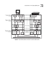
Figure 1-2   

User Interfaces and Protocols Used to Access the LANplex System

Application Layer

Transport Layer

Network Layer

Data-link &

Physical Layers

SNMP

Managers

SNMP

TCP

Administration

Console Application

UDP

Ethernet

FDDI

SMT

TCP

UDP

telnet,

rlogin, ftp

SNMP/SMT
Proxy Agent

SNMP

Agent

IP

IP

Serial Line

Serial Line

Ethernet

FDDI

SMT

Administration

Console

Discussed in Chapter 2:

User Access: What

You See

Discussed in Chapter 3:

Management Access:

Protocols

Discussed in Chapter 4:

Physical Access: Ports

and Cabling

telnet,

rlogin, ftp

Terminal

Emulation

LANplex

®


2500 system

Summary of Contents for LANPLEX 2500

Page 1: ...LANPLEX 2500 OPERATION GUIDE Part No 801 00344 000 Published November 1996 Revision 03...

Page 2: ...tware Restricted Rights Clause at 48 C F R 52 227 19 and the limitations set forth in 3Com Corporation s standard commercial agreement for the software Unpublished rights reserved under the copyright...

Page 3: ...2500 System 1 1 User Interfaces and the LANplex 2500 System 1 2 2 USER ACCESS WHAT YOU SEE About the User Interfaces to the LANplex 2500 2 1 The Built in LANplex Administration Console 2 3 External Ne...

Page 4: ...How a Bridge Ages Addresses 5 3 Packet Forwarding 5 4 Spanning Tree and the Bridged Network 5 6 Packet Looping in a Bridged Network 5 6 The Spanning Tree Algorithm 5 7 How the Spanning Tree Algorithm...

Page 5: ...Port Groups From a Packet Filter 7 11 Example Using Address Groups in a Packet Filter 7 11 Globally Administering Packet Filters 7 16 8 LANPLEX BRIDGING EXTENSIONS Multicast Packet Firewalls 8 1 IP Fr...

Page 6: ...Virtual Channels 11 6 ATM Protocol Architecture 11 7 The Physical Layer 11 8 SONET Physical Layer Interface 11 8 The ATM Layer 11 8 Quality of Service 11 8 The ATM Adaptation Layer AAL 11 9 AAL Sublay...

Page 7: ...s B 1 3Com Bulletin Board Service B 1 Access by Analog Modem B 1 Access by Digital Modem B 2 World Wide Web Site B 2 3ComForum on CompuServe Online Service B 2 3ComFactsSM Automated Fax Service B 3 Su...

Page 8: ...ase notes shipped with your product differs from the information in this guide follow the release notes How to Use This Guide Table 1 shows where to find specific information Table 1 Locating Informat...

Page 9: ...ossary Table 1 Locating Information in This Guide continued If you are looking for information on Turn to Table 2 Notice Icons Icon Type Description Information Note Information notes call attention t...

Page 10: ...have been supplied and you must enter the command as shown Example The following command enables Spanning Tree bridge stpState enabled screen display This typeface represents displays that appear on y...

Page 11: ...sary for planning your configuration and for installing cabling powering up configuring management access and troubleshooting your LANplex system Shipped with your system Part No 801 00335 000 LANplex...

Page 12: ...o 801 000319 000 Module Installation Guides Provide an overview installation instructions LED status information and pin out information for the particular option module Shipped with individual module...

Page 13: ...I Chapter 1 Management and Administration Overview Chapter 2 User Access What You See Chapter 3 Management Access Protocols Chapter 4 Physical Access Ports and Cabling MANAGEMENT AND ADMINISTRATION...

Page 14: ......

Page 15: ...ANplex 2500 system combines high port density Ethernet switching Ethernet to FDDI bridging Fast Ethernet switching FDDI switching and ATM switching in an integrated system You can configure much of th...

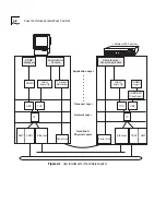
Page 16: ...d physical interfaces User Interfaces and the LANplex 2500 System Figure 1 2 shows how the levels of the OSI reference model are integrated in the management and administration device as well as in th...

Page 17: ...s SNMP TCP Administration Console Application UDP Ethernet FDDI SMT TCP UDP telnet rlogin ftp SNMP SMT Proxy Agent SNMP Agent IP IP Serial Line Serial Line Ethernet FDDI SMT Administration Console Dis...

Page 18: ...1 4 CHAPTER 1 LANPLEX MANAGEMENT AND ADMINISTRATION OVERVIEW...

Page 19: ...ment functions About the User Interfaces to the LANplex 2500 You can use the following applications as the user interface to your LANplex system The built in LANplex Administration Console External SN...

Page 20: ...rt Layer Network Layer Data link Physical Layers SNMP TCP UDP FDDI SMT TCP UDP telnet rlogin ftp SNMP SMT Proxy Agent SNMP Agent IP Serial Line Serial Line FDDI SMT telnet rlogin ftp Terminal Emulatio...

Page 21: ...Translation addressThreshold Set the bridge address threshold agingTime Set the bridge aging time stpState Enable Disable Spanning Tree on a bridge stpPriority Set the Spanning Tree bridge priority s...

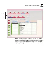
Page 22: ...nd get statistics about each device Transcend Enterprise Manager software helps you monitor and manage the performance of your switching hub based network You can also display statistical graphs showi...

Page 23: ...atus View Software Because the LANplex system is based on SNMP standards you can manage your system using third party SNMP based network manager applications such as Sun Microsystems SunNet Manager He...

Page 24: ...d from your LANplex system About LANplex 2500 Protocols The LANplex 2500 system uses the following protocols Virtual terminal protocols such as rlogin and telnet Simple Network Management Protocol SNM...

Page 25: ...ort Layer Network Layer Data link Physical Layers Ethernet FDDI SMT Serial Line Serial Line Ethernet FDDI SMT SNMP Managers Administration Console Application Administration Console SNMP TCP UDP TCP U...

Page 26: ...with a virtual terminal protocol Within the Administration Console you configure an IP address by defining an IP interface Terminal emulation differs from a virtual terminal protocol in that you must...

Page 27: ...as Transcend Enterprise Manager software The agent also reports network events SNMP MIBs You can access the information that is defined in industry standard and enterprise specific proprietary Managem...

Page 28: ...the LANplex system For descriptions of these traps see the ASN 1 MIB definition files included with your software release Table 3 1 SNMP Traps in the LANplex 2500 system Group Trap MIB II coldStart au...

Page 29: ...e the LANplex system s SNMP community strings to match those used by the SNMP manager For information on how to configure community strings see the LANplex 2500 Administration Console User Guide SMT S...

Page 30: ...t Your LANplex system contains a proxy agent that translates between SNMP and FDDI SMT It allows a network management station that is not necessarily connected directly to an FDDI LAN to manage FDDI e...

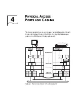
Page 31: ...el environment Figure 4 1 Physical Access Options for the LANplex system Application Layer Transport Layer Network Layer Data link Physical Layers SNMP Managers Administration Console Application Admi...

Page 32: ...ional If you are using a dedicated network outside your system and its attached LANs for management data then you are managing your network out of band For more information on system management see th...

Page 33: ...ress is assigned to the ports The LANplex SNMP agent can also be accessed through these interfaces The following Ethernet port types are possible 10BASE T RJ 21 10BASE T RJ 45 10BASE 5 AUI 10BASE FL 1...

Page 34: ...PORTS AND CABLING Figure 4 3 shows management access through any Ethernet or FDDI port Figure 4 3 Access to the LANplex System Through any Ethernet or FDDI Port Workstation Workstation FDDI port Ethe...

Page 35: ...II Chapter 5 Transparent Bridging Chapter 6 Express Switching Chapter 7 User defined Packet Filtering Chapter 8 Bridging Extensions BRIDGING TECHNOLOGY...

Page 36: ...ced What Makes a Bridge 802 1d Compliant Transparent bridging has been adopted for standardization by the IEEE and is defined in the IEEE 802 1d specification The IEEE 802 1d bridging standard specifi...

Page 37: ...e packet s source address in the address table and does one of the following If the source address is known to the bridge then the bridge updates the source address entry in the address table and veri...

Page 38: ...in its address table Address aging although typically an efficient means of maintaining a current address table can create problems when regularly used stations on the network do not transmit periodic...

Page 39: ...ge identifies the port on which the destination address is located If the destination bridge port is different from the bridge port on which the packet was received then the packet is forwarded to the...

Page 40: ...ng station Address Table Transmitting station Bridge Filtering 1 2 3 4 1 Filtered packet enters bridge 2 Packet s destination address is compared to bridge s address table 3 Address is known but desti...

Page 41: ...mplement redundant links so that although individual bridges might fail the networks data pathways between stations remain active Loops can also occur by accident For instance when more than one bridg...

Page 42: ...LANs and therefore between any two stations See Figure 5 4 A port in the blocking state neither forwards nor receives data packets After the algorithm eliminates extra paths the network configuration...

Page 43: ...Us at work The CBPDUs help the bridges establish a hierarchy among themselves or a calling order for the purposes of creating a loopless network Based on the information in the CBPDUs the bridges elec...

Page 44: ...oot bridge Its function is to forward packets between that LAN and the path to the root bridge For this reason the root bridge is always the designated bridge for its attached LANs The port through wh...

Page 45: ...he port priority plus the number of the port from which the transmitting bridge sent a CBPDU It is only used in the Spanning Tree calculation if the root IDs transmitting bridge IDs and costs when com...

Page 46: ...one bridge interprets CBPDUs thus contributing to the Spanning Tree configuration For purposes of this case the following convention is used to depict a CBPDU root ID cost transmitter ID 1 When Spann...

Page 47: ...mallest cost to the root This port becomes the root port 5 Now that the bridge knows the contents of its own CBPDU it can compare this updated CBPDU with the ones received on its other ports If the br...

Page 48: ...it their CBPDUs receive each other s CBPDUs and compare the CBPDUs to each other Because Bridge B has the lowest root ID of all the bridges it becomes the root See Figure 5 8 LAN 5 Bridge A Bridge B B...

Page 49: ...e root bridge The cost depends on 1 the port s path cost and 2 the root path cost of the designated bridge for the LAN to which this port is attached LAN 5 Bridge A Bridge B Bridge C Bridge D Bridge E...

Page 50: ...also the designated bridge for LANs 1 2 and 5 A designated bridge must still be determined for LANs 3 4 and 6 Because Bridges C D and F are all attached to LAN 3 one of them must be the designated bri...

Page 51: ...listening state except that data packets are received on that port for the purpose of learning the stations that are attached to that port After spending the specified time in this state if the bridge...

Page 52: ...becomes disabled Figure 5 9 Factors Involved in Spanning Tree Port State Transitions Disabled A port is disabled when Spanning Tree Protocol has been turned off for that specific port or when the por...

Page 53: ...on is broadcast to all the bridges It transmits this CBPDU for a fixed amount of time to ensure that all bridges are informed of the topology change If a port changes from the blocking state to the fo...

Page 54: ...as the backbone port A unicast frame is forwarded from the backbone port only if the bridge has learned the destination address on another port Conversely a unicast frame is forwarded to the backbone...

Page 55: ...s that contain tree or mesh topologies that mix extended Ethernet and FDDI networks See Figure 6 2 Figure 6 2 Traditional Transparent Bridging Tree Topology LANplex 2500 system Server Workstations LAN...

Page 56: ...ound the bridge behaves differently from a traditional bridge For example A traditional bridge would flood the packet to all ports except the one on which it was received In Express Switching mode the...

Page 57: ...ected to the backbone until the bridge has learned that station s address Therefore in certain circumstances a station must speak before it can be spoken to Source address group information relating t...

Page 58: ...y taking advantage of this powerful feature you can improve network performance provide additional security or logically segment your network to support virtual workgroups Designing a Packet Filter Th...

Page 59: ...et to the network segment it originated from if it does not meet the forwarding criteria Table 7 1 Some Simple Packet Filter Operands Operand Description Constant A literal value A constant can be 1 2...

Page 60: ...es show you how to define and apply packet filters to ports and paths on your network Example 1 isolates protocols in a network Example 2 shows a more complex version of the filter in the first exampl...

Page 61: ...n workstations but Sun workstations cannot use AppleTalk protocol to communicate with the Macintoshes Without any packet filtering AppleTalk broadcasts would be bridged to the IP segments Even some un...

Page 62: ...byte value at offset 12 in the Ethernet packet Operand 2 is the type field constant value for AppleTalk protocol Operator is equal The filter is installed as shown in Figure 7 3 Figure 7 3 Example of...

Page 63: ...eld is Greater than 1500 then the packet is an Ethernet packet and the value is interpreted as the type field Less than or equal to 1500 then the packet is an 802 3 packet and the value is interpreted...

Page 64: ...9b Operand 1 is the SNAP field which is a 6 byte value at offset 16 of the AppleTalk Phase II packet Operand 2 is the constant value for the AppleTalk Phase II SNAP field 0x03080007809b Operator is eq...

Page 65: ...access only to a specific network resource Stations that have access only to a group of network segments Network segments whose attached stations can communicate only with each other What Is an Addre...

Page 66: ...re up to 32 port groups per LANplex 2500 system When a port is added to a group the port is inserted into a port table on the associated system Each port table entry contains a 32 bit group mask As wi...

Page 67: ...Port Table Port FDDI port 1 Ethernet port 1 Ethernet port 2 Ethernet port 3 Ethernet port 4 Ethernet port 5 Ethernet port 6 Ethernet port 7 Ethernet port 8 Group Mask 32 bits 0f400000 00000000 000006...

Page 68: ...are direct attach Engineering B group spread over four segments two of which are direct attach Accounting data server that contains accounting information such as payroll revenue data purchase orders...

Page 69: ...ing B group must be able to communicate only with each other and Compute server B Users in all three groups must be able to communicate only with the Mail server LANplex 2500 system A Bridge relay Bri...

Page 70: ...nd group masks but the port numbers are different numbers The address 00 01 02 03 04 03 00 01 02 03 04 0a 00 01 02 03 04 04 00 01 02 03 04 0b 00 01 02 03 04 05 00 01 02 03 04 0c 00 01 02 03 04 06 00 0...

Page 71: ...address group mask AND destination address group mask Operand 1 is the source address group mask Operand 2 is the destination address group mask Operator is bit wise AND Expression 2 Expression 1 resu...

Page 72: ...rt 1 FDDI Port 1 Ethernet Port 6 Ethernet Port 2 Ethernet Port 2 Ethernet Port 1 Ethernet Port 3 Ethernet Port 5 FDDI Port 1 FDDI Port 1 Ethernet Port 7 Ethernet Port 5 unknown FDDI Port 1 Ethernet Po...

Page 73: ...ecially important for address group distribution because the related stations are often distributed across many different network segments See the LANplex 2500 Administration Console User Guide Comput...

Page 74: ...s to the repeated transmission of a high rate of broadcast or other multicast packets onto the network Several scenarios can result in a multicast storm These include Faulty protocol implementations U...

Page 75: ...he maximum length of the information field in an FDDI packet is 4478 bytes but the maximum length of the information field in an Ethernet packet is only 1500 bytes Therefore any packet sourced from an...

Page 76: ...a result you typically set the bridge aging timer to a relatively short interval to reduce the likelihood that an address is learned on more than one bridge port at a time Unfortunately the side effe...

Page 77: ...it The address is never aged and can never be learned on a different Ethernet port If a packet with a statically configured source address is received on a port that differs from the address s assign...

Page 78: ...III Chapter 9 FDDI Overview and Implementation Chapter 10 FDDI Networks FDDI TECHNOLOGY...

Page 79: ...ensive computing environments by providing increased throughput greater network size improved reliability and superior fault tolerance Here are some facts about FDDI FDDI uses optical fiber as its tra...

Page 80: ...on among the stations Station Management SMT SMT specifies the FDDI station and ring configurations initialization and maintenance of station to station connections and the control required for the pr...

Page 81: ...PMD pair that connects to the fiber media and that provides one end of a physical connection with another station Ports located at both ends of a physical connection determine the characteristics of t...

Page 82: ...inations by scheduling and performing all data transfers MAC Services Some of the services that the MAC performs include frame repetition and reception frame removal frame validity criteria checking t...

Page 83: ...itions may exist in parts of the network that may cause the path to be in a different ring Local path One or more segments of the rings other than the primary ring and secondary ring that pass through...

Page 84: ...Any station or concentrator that has two physical con nections to an FDDI network This type of attachment can accommodate a dual counter rotating ring A dual attachment station has one A B port pair a...

Page 85: ...gure 9 2 Examples of FDDI Configurations SAS Duplex fiber cable FDDI dual ding M DAC A B M M A B S S SAS S DAC DAC SAC A port B port Master port Slave port A B M S SM DAS B M M A M M SAS S S SAS NAC D...

Page 86: ...t maintenance Configuration Management CFM Interconnects PHYs and MACs on paths to achieve proper station configuration and network topology Ring Management RMT Manages a MAC s operation in an FDDI ri...

Page 87: ...learn the addresses of the logical neighbors of each MAC in a station This information is useful in detecting and isolating network faults Parameter Management Performs the remote management of stati...

Page 88: ...out having to upgrade all clients to FDDI You can install your system into many possible FDDI configurations Figure 9 3 shows LANplex systems attached to an FDDI dual ring The connection to the dual r...

Page 89: ...2500 system A B A B A B B A A B A B B A B A B A B A SAS server SAS server FDDI link DAS server LANplex 2500 system NETBuilder II router FDDI dual ring Duplex fiber cable LANplex 2500 system LANplex 2...

Page 90: ...erences from other types of LANs FDDI networks can provide a network backbone between buildings on a campus or within a multilevel high rise building An FDDI network can Meet the networking needs of t...

Page 91: ...hysical topology is defined by the arrangement and interconnection of its nodes The FDDI physical topology is a ring of trees See Figure 10 1 Figure 10 1 Physical Topology Logical topology A network s...

Page 92: ...lation and allows centralized management See Figure 10 3 Figure 10 3 Ring of Trees All physical connections in an FDDI topology are duplex links a pair of insulated fiber optic conductors Both the FDD...

Page 93: ...so be used to carry data but it is typically used as a backup in case there is a connectivity problem in the primary ring or in one of the nodes on the ring When a single fault takes place on an FDDI...

Page 94: ...a single MAC node B to A Normal dual ring peer connection B to B Undesirable peer connection that creates twisted primary and secondary rings notify SMT B to S Undesirable peer connection that create...

Page 95: ...ng dual homing can determine a station s operation by setting the appropriate configuration policy The dual homed station can be configured with both links active or with one link active and one conne...

Page 96: ...For additional information about dual homing see the LANplex 2500 Getting Started guide Secondary system Link set by configuration policy Dual homed node DAS Primary link Primary system Duplex fiber...

Page 97: ...IV Chapter 11 ATM Networks ATM TECHNOLOGY...

Page 98: ...of this study is the Broadband Integrated Services Digital Network BISDN BISDN services provide high speed channels for transmitting digitized voice data video and multimedia traffic Asynchronous Tran...

Page 99: ...t the need for a prior connection setup between the sender and receiver LAN data is transmitted using the Media Access Control MAC addresses in each packet to identify end stations ATM is a connection...

Page 100: ...all fixed length units called cells Each ATM cell comprises two parts a 5 byte header and a 48 byte information field payload Header Figure 11 2 shows the structure of the UNI ATM cell The header cont...

Page 101: ...ction Payload Type Indicator PTI A 3 bit field that indicates if the cell contains user information or connection associated layer management information Cell Loss Priority CLP Indicates that under co...

Page 102: ...simply connects two endpoints A point to multipoint connection is a unidirectional connection between two or more endpoints One ATM endpoint is designated as the root and serves as the source node in...

Page 103: ...d the VCI that specify the virtual connection VC over which the cell should be forwarded See Figure 11 3 Figure 11 3 Virtual Channels and Virtual Paths The VPI and VCI establish only the connections b...

Page 104: ...nce Model Application Data ATM Layers VPI VCI Table Application Data ATM Layers VPI VCI Table ATM switch VPI VCI Table ATM switch VPI VCI Table Virtual Path Virtual Channel Virtual Path Virtual Channe...

Page 105: ...envelope necessary for the transport of ATM cells The LANplex system uses SONET OC 3 as the Physical Layer interface for the ATM network The ATM Layer The ATM Layer provides a single mode of transport...

Page 106: ...formation field with data This AAL makes ATM look like high speed frame relay It also assumes that only one message is crossing the UNI at a time That is multiple end users at one location cannot inte...

Page 107: ...ports all items identified for the user side device in a private UNI as defined in the UNI 3 0 specification plus additional objects listed in UNI version 3 1 for the ILMI MIB ATM Address Registration...

Page 108: ...significance of LAN to ATM conversion functions Two methods that can be used to interconnect LANs over an ATM network are The first method Classical IP over ATM implements IP natively over ATM which e...

Page 109: ...transparent to the ATM network and to legacy LAN devices In addition it maps the MAC address based networking protocols into ATM virtual connections To provide a connectionless MAC service on top of A...

Page 110: ...LAN emulation service server Each LAN is composed of all nodes that have joined a particular LAN emulation service An end system is configured as a member of a single LAN emulation service while an i...

Page 111: ...ifferent LAN segments must be bridged or routed This means that each LAN emulation service is required to forward traffic between nodes on segments A and B to the router Membership in an ATM LAN segme...

Page 112: ...ng configuration database and information provided by clients the LECS assigns any client requesting configuration information to a specific Emulated LAN service by giving the client the LES s ATM add...

Page 113: ...e configuring ATM in your LANplex 2500 system you should take these steps to confirm that your ATM connection is established Check the ATM link status Verify LANplex address registration is operationa...

Page 114: ...xtended Software only 2 Define the Broadcast and Unknown Server 3 Define the LAN Emulation Server For information on configuring ELANs in your LANplex 2500 system See Chapter 9 Administering ATM in th...

Page 115: ...on the software type installed For information on eliminating bridge loops in an ELAN configuration using either LANplex Intelligent Switching software or LANplex Extended Switching software see Chapt...

Page 116: ...V Appendix A SNMP MIB Support Appendix B Technical Support APPENDIXES...

Page 117: ...attribute additions and deletions that may occur from release to release are documented in the Installation and Release Notes Copies of ASN 1 files are provided for each of the supported compilers des...

Page 118: ...SMT 7 3 MIB RFC 1512 lec mib LEC MIB af lane 0044 00 The following LEC MIB attributes are not supported dot1dBase Group dot1dBasePortDelayExceedDiscards dot1dSr Group dot1dTp Group dot1dFdbTable dot1d...

Page 119: ...following LANplex Optional FDDI MIB attributes are not supported mib2 mib MIB II RFC 1213 The following MIB II attributes are not supported srbridge mib Source Routing MIB RFC1525 The following generi...

Page 120: ...has no effect on the output produced by the MOSY compiler HP Openview version 3 1 mib2schema with SunNet Manager version 2 0 The MIB file fddiSmt7 mib produces the following warning messages when comp...

Page 121: ...ts as well as technical articles This service is available via modem or ISDN 24 hours a day seven days a week Access by Analog Modem To reach the service by modem set your modem to 8 data bits no pari...

Page 122: ...is service features news and information about 3Com products customer service and support 3Com s latest news releases selected articles from 3TECH journal 3Com s award winning technical journal and mo...

Page 123: ...anning installation hardware maintenance application training and support services When you contact your network supplier for assistance have the following information ready Diagnostic error messages...

Page 124: ...ned to the sender unopened at the sender s expense To obtain an RMA number call or fax Country Telephone Number Country Telephone Number Australia 1 800 678 515 Mexico 525 532 0591 Belgium 0800 71429...

Page 125: ...tions Datagram Delivery Protocol and AppleTalk Session Protocol addressing Name Binding Protocol file sharing AppleShare and remote access AppleTalk Remote Access application layer The uppermost layer...

Page 126: ...t that connects LANs allowing communication between devices on separate LANs Bridges are protocol independent but hardware specific with communication limited to the data link layer and physical layer...

Page 127: ...the concatenation of ATM Layer links in order to provide an end to end information transfer capability to access points connectionless communications A form of packet switching that relies on global a...

Page 128: ...reated using the LANE specifications See also LANE ESI End system identifier A field in the ATM NSAP address that contains the MAC address optional of the end system Ethernet A CSMA CD 10Mbps local ar...

Page 129: ...e need for more speed and reliability than is currently available in other standard LANs Its recent completion is a major factor contributing to the expected acceptance and widespread use of optical f...

Page 130: ...ill be forwarded ISO International Standards Organization A multinational organization that sets computer communication and other standards The ISO defined the OSI seven layer reference model for comp...

Page 131: ...sents the specifications and services provided for conforming FDDI attachment devices MAC specifies access to the medium including addressing data checking and data framing See also data link layer MI...

Page 132: ...sparent bridge This filtering can improve network performance provide additional security and logically segment a network to support virtual workgroups PDU Protocol data unit A unit of data specified...

Page 133: ...ted to an exterior modem See also modem repeater An FDDI node that serves as a two way relay of the optical signals in an FDDI network A repeater does not have MACs or concentrator functionality ring...

Page 134: ...e trunk ring through the B port and exits through the A port See also primary ring server A computer that provides clients with application and network services Servers are shared by multiple users SM...

Page 135: ...2 1d UME UNI management entity The UMI is the code residing in the ATM devices at each end of a UNI circuit that implements the management interface to the ATM network UNI User to network interface Th...

Page 136: ...6 authenticationFailure 3 5 B BISDN 11 1 blocking port state 5 16 bridge aging timer 8 3 designated 5 8 least cost path 5 9 root 5 8 Bridge Protocol Data Unit BPDU 5 18 bridging configuration messages...

Page 137: ...r flooding packet 5 5 8 3 forwarding packets 5 4 6 3 port state 5 16 fragmentation See IP fragmentation frame based protocols 9 9 G generic flow control 11 4 groups address See address group groups po...

Page 138: ...eference Model and FDDI 9 2 out of band management 4 2 P packet fields for operands 7 2 flooding 5 5 8 3 forwarding 5 4 6 2 fragmentation 8 2 looping 5 6 reduced flooding 8 3 packet filter address gro...

Page 139: ...al support B 1 telnet 3 3 terminal emulation 3 3 virtual 3 3 token 9 4 Topology Change Flag 5 18 topology FDDI 10 2 to 10 4 Transcend Enterprise Manager SNMP community strings and 3 6 Transcend Enterp...

Reviews: