Installation Manual
H3C S9500 Series Routing Switches
Appendix A Cable Management
A-1
Appendix A Cable Management
A.1 Correct Use of Labels
Before binding the cables, you should fill in the labels for them correctly and stick them
to the right position on the cables. For details, refer to the description of label usage in
Appendix A Engineering Labels for Cables.
A.2 Cable Management Requirements
z
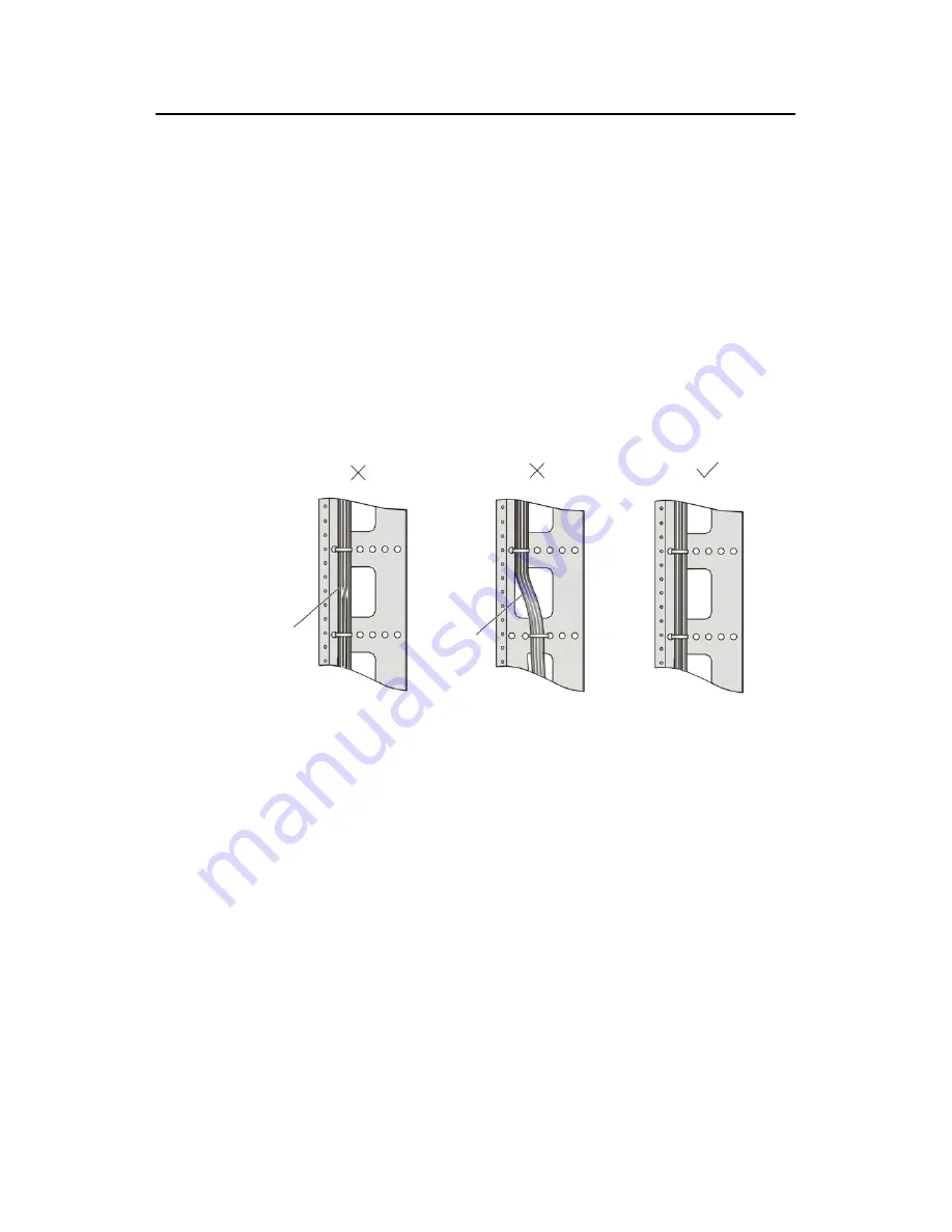
Bind and put the cables inside the cabinet in a straight and neat way. No
intertwinement or bending is allowed.
缠绕
弯曲
缠绕
弯曲
Intertwined
Bent
缠绕
弯曲
缠绕
弯曲
缠绕
弯曲
缠绕
弯曲
Intertwined
Bent
Figure A-1
Cable binding example I
z
The bend radius of cable body cannot be less than twice of the cable diameter.
The bend radius of the cable cannot be less than 5 times of its diameter at the
place where it is led out of the connector;
z
Different cables (power cord, signal cable, PGND wire, etc.) should be cabled and
bound separately rather than together in the cabinet. If they are close to each
other, you can cable them in cross-shape. For parallel cabling, the space between
power cord and signal cable should be no less than 30 mm (1.2 in);
z
The cable binding rack and cabling channel inside and outside the cabinet should
be smooth and without sharp edges or tips;
z
The metal cable management hole should have a smooth and fully rounded
surface or wear a insulating bush;
z
Use the right type of ties to bind the cables. Do not bind cables with joined ties.
The following types of ties are available currently: 100 × 2.5 mm (3.9 in × 0.1 in),
150 × 3.6 mm (5.9 × 0.1 in), 300 ×3.6 mm (11.8 × 0.1 in), 530 × 9 mm (20.9 × 0.4
in), and 580 × 13 mm (22.8 × 0.5 in);


