Installation Manual
H3C S9500 Series Routing Switches
Chapter 2 Installation Preparations
2-16
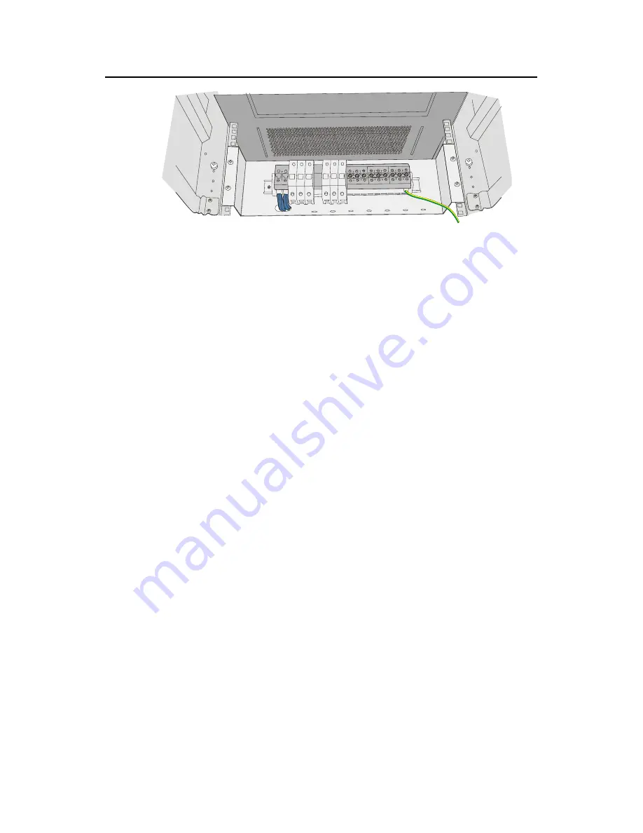
Figure 2-12
Diagram for fixing the power distribution box to the rear of the N68 cabinet
4) You can make the air switches to supply power to DC power modules by
connecting the lower terminals of the air switches to DC power input terminals and
supply voltages to DC power. (Refer to Figure 2-9 for detail. Note that the
diameters of the cables need to be 6 mm
2
or 10 mm
2
.)
5) You can use the BGND and PGND terminal blocks as needed. The rightmost
PGND terminals must be connected to the cabinet using 6 mm
2
cables, as
illustrated in Figure 2-12.
6) Fasten the connected power cables with a wire and secure them onto the power
distribution box.
7)
Use two 16 mm
2
cables to connect the cabinet and the DC power distribution box.
You need to connect the two cables to the leftmost terminal blocks of the cabinet,
as illustrated in Figure 2-9.


