Installation Manual
H3C S9500 Series Routing Switches
Chapter 3 Switch Installation
3-9
(1)
(2)
(6)
(3)
(4)
(7)
(8)
(9)
(12)
(5)
(11)
(10)
(1)
(2)
(6)
(3)
(4)
(7)
(8)
(9)
(12)
(5)
(11)
(10)
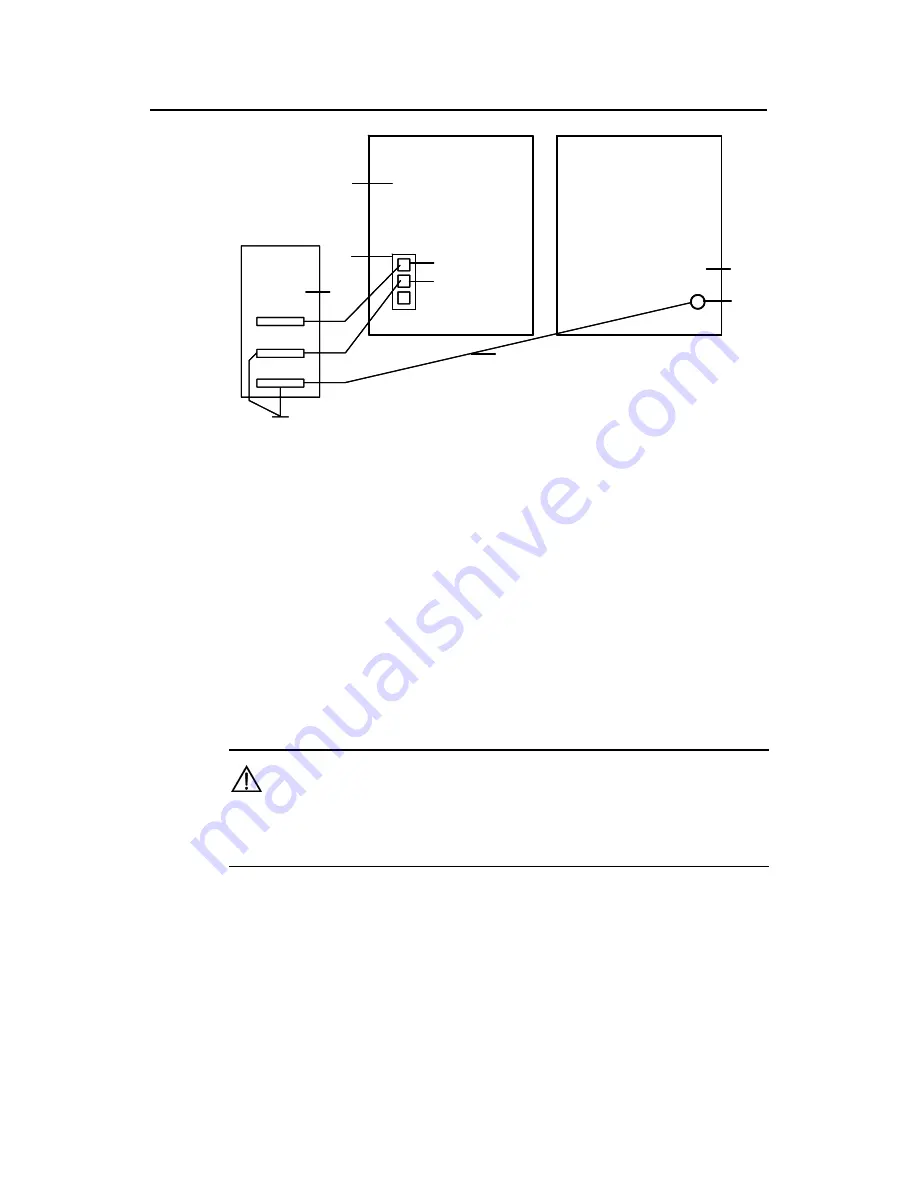
(1) Front panel of the switch
(2) DC power input
(3) NEG terminal
(4) RTN terminal
(5) PDF
(6) -48V strip
(7) RTN strip
(8) PGND strip
(9) Earth ground
(10) PGND wire
(11) Grounding screw
(12) Rear panel of the switch
Figure 3-8
Ground the switch through the PGND strip of the PDF
3.6 Installing a PSU
3.6.1 Installation Preparation
z
Wear an ESD-preventive wrist strap and verify the ESD-preventive wrist strap is
properly grounded.
z
If there is a filler panel in the position where you will install a PSU, remove the filler
panel.
Caution:
When you move a PSU, hold its bottom with one hand. Do not move it by just holding its
handle. Otherwise, the PSU may be damaged.
3.6.2 Installation Procedure
I. Removing a PSU other than NEPS3500-A
The following procedure applies to all NEPS PSUs except NEPS3500-A.


