Installation Manual
H3C S9500 Series Routing Switches
Chapter 3 Switch Installation
3-17
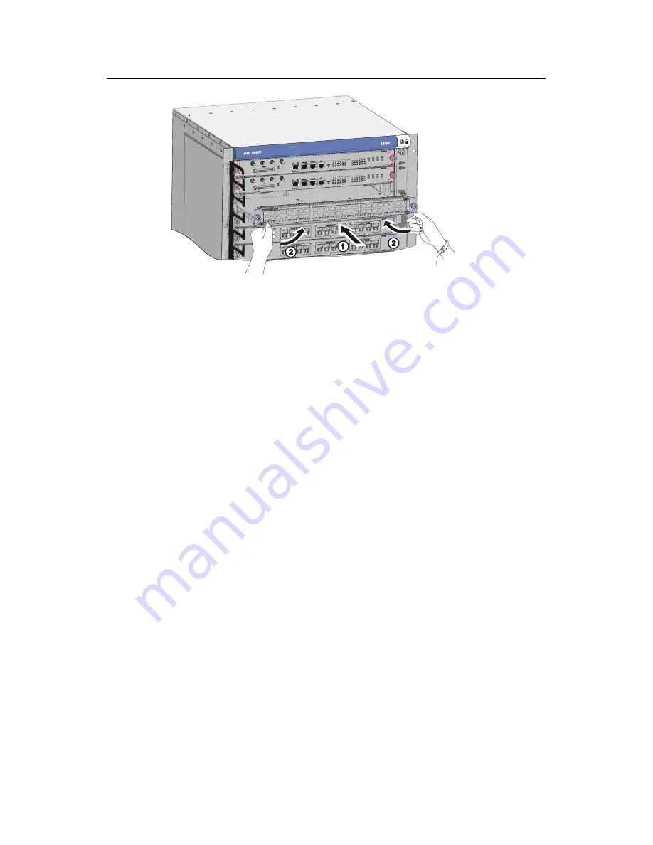
Figure 3-18
Install an LPU
3) Fix the LPU by fastening the mounting screws on the LPU with a Phillips
screwdriver.
3.8 Installing PoE Power Supply
The S9505/S9508/S9512 uses PSE4500-A as an external PoE power supply, which is
connected to the switch through the PoE power entry module at the front bottom of the
switch to provide power for connected powered devices (PDs).
The S9502 uses PSE2500-A1 as an external PoE power supply, which is connected to
the switch through the PoE filter at the back of the switch chassis to provide power for
connected PDs.
The following introduces the installation of PoE power supply on the S9505.
3.8.1 Installation Procedure
z
Wear the ESD-preventive wrist strap, making sure that it is properly grounded.
z
Remove blank filler panels in the power supply area if applicable.
3.8.2 Installing the PoE Power Entry Module
The PoE power entry module is hot-swappable.
Follow the steps below to install the PoE power entry module:
1)
Unpack the PoE power entry module, which is shown in Figure 3-19.


