Installation Manual
H3C S9500 Series Routing Switches
Chapter 3 Switch Installation
3-20
3) Connect the PGND OT terminal of the black DC power cable to the RTN (
+
)
terminal of the PoE power entry module and fasten the mounting screw; connect
the other end to the RTN (+) terminal of the external PoE power supply.
Caution:
z
Observe the polarity signs on devices and connect the cables correctly.
z
Choose right cables based on the load.
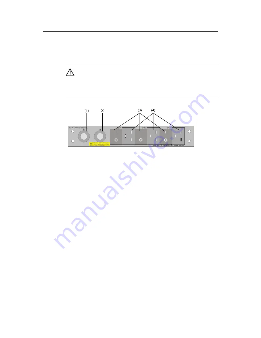
(1) NEG(–) terminal of DC output
(2) RTN(+) terminal of DC output
(3) AC input switch
(4) AC input socket
Figure 3-22
Input/output of external PoE power supply
3.9 Connecting Interface Cables
3.9.1 Cable Routing Recommendations
Interface cables and power cables should be routed separately. You can bind long
cables with cable ties. For specific binding requirements, refer to Appendix A “Binding
Cables”.
I. Workbench-mounted switch
All interface cables are routed to the left side (the cable management bracket) of the
chassis, and power cables are routed to the front of the chassis.
II. Rack-Mounted switch
z
The interface cables are bound on the cable management bracket on the left side
of the chassis and are routed up or down to pass through the chassis top or the
raised floor, depending on the available equipment room condition (that is, signal
cables are routed into the chassis either from the cabling racks on the chassis top
or from the cabling trough under the floor).
z
All digital signal cable connectors should be put at the bottom of the cabinet. Do
not put them outside the cabinet.


