Installation Manual
H3C S9500 Series Routing Switches
Chapter 3 Switch Installation
3-21
z
Power cables run along the left-front of the chassis and out of the chassis either
from the top or the raised floor, depending on the equipment room conditions (PDF,
lightning protection box, and terminal block, etc.) in the equipment room.
Caution:
z
Do not bind cables at the air exhaust vents of the switch to prevent premature cable
aging.
z
Fix cables as near the device as possible. The cables between the fixing point and
device interfaces must be bound loosely.
z
To identify cables, you can stick labels on them. For more information, refer to
Appendix B “Engineering Labels for Cables”.
3.9.2 Connecting Console Cable
I. Introduction
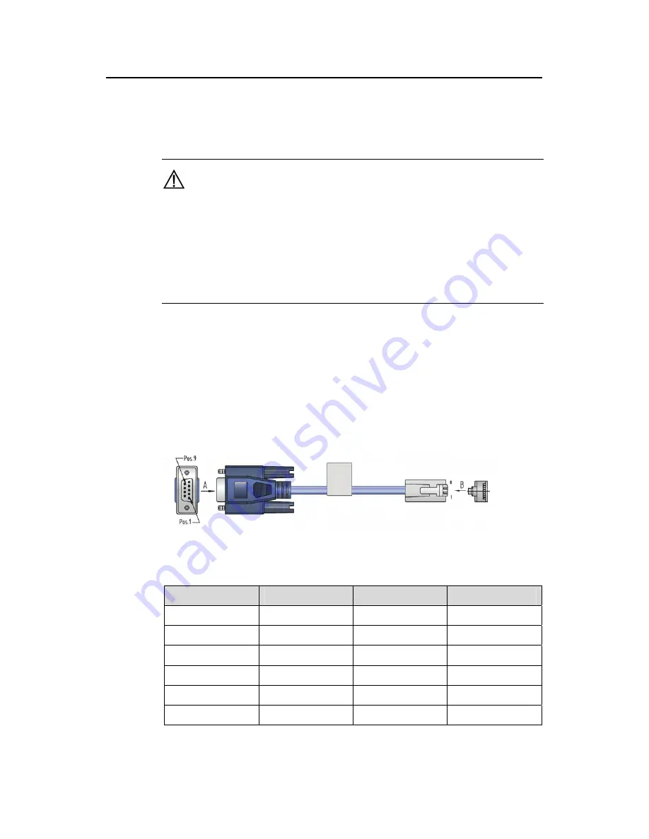
Console cable is an 8-core shielded cable. At one end of the cable is a crimped RJ-45
connector that is to be plugged into the console port of the switch. At the other end of
the cable is a DB-9 (female) connector. You can plug it into the 9-pin (male) serial port
on the console terminal. The following figure illustrates the console cable.
Figure 3-23
Console cable
Table 3-3
Console cable pinouts
RJ-45
Signal
DB-9
Signal
1 RTS
8 CTS
2 DTR
6 DSR
3 TXD
2 RXD
4 CD
5 SG
5 GND
5 SG
6 RXD
3 TXD


