Installing NBX 100 NCP and Other Cards
149
Installing Cable
Guides
Each NBX 100 chassis comes with a package of plastic cable guides which
clip into the chassis beside each card slot. These guides can help you keep
the LAN and CO line wires organized.
Snap the guides into the holes to the right of the card slots. (See
Figure 32).
Installing a
Single-Port Analog
Terminal Adapter
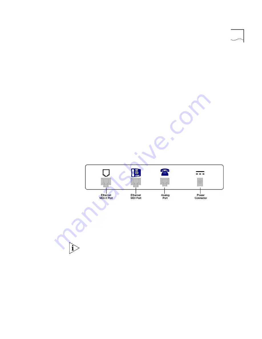
If you are installing Single-Port Analog Terminal Adapters (ATAs), install
them after installing the cards in the chassis. Perform the following steps
to install the Single-Port ATA.
1
Connect the analog telephone or fax device to the Analog Port on the
ATA.
2
Connect the Ethernet Hub MDI-X port on the ATA to the LAN at the site
of the NBX 100. Connect that same port to the 8-port Hub card in the
NBX 100 chassis or to any hub on the network.
Figure 36
Single-Port ATA Connectors — Rear View
3
You can optionally connect a local PC (or other Ethernet device) to the
Ethernet MDI Port on the ATA. This serves as a hub to connect the local
PC to the LAN.
4
Connect the AC Power Adapter to the AC Power Connector on the ATA,
then plug the adapter into a wall outlet.
The Single-Port Analog Terminal Adapter may require a telephone
connector for use outside North America. The part number is
3C10120-xx, where xx is the country code. Contact your supplier for
more information on country-specific requirements.
Installing a Power
Adapter
If you are installing a power adapter using the power line kit, the cable
length
can be anything within the 10BASE-T specification, including the
length from the patch panel to the brick and then to the telephone. In
10BASE-T, the maximum segment is 100m (328 feet) so if the length from
the patch panel to the brick is 28 feet, then 300 feet is supported.
Summary of Contents for NBX 100
Page 1: ...http www 3com com NBX 100 Installation Guide Release 2 8 Part No 900 0026 01 November 2000 ...
Page 12: ......
Page 18: ...18 ABOUT THIS GUIDE ...
Page 128: ...128 CHAPTER 2 CONFIGURING THE DIAL PLAN ...
Page 196: ...196 CHAPTER 4 CONFIGURING NBX 100 SYSTEM LEVEL SETTINGS ...
Page 238: ...238 CHAPTER 6 SETTING UP USERS AND FEATURES 6 Click Apply to effect the changes 7 Click OK ...
Page 268: ...268 CHAPTER 7 CONFIGURING DIGITAL LINE CARDS T1 E1 AND BRI CARDS ...
Page 286: ...286 APPENDIX A NBX 100 SYSTEM SPECIFICATIONS ...
Page 290: ...290 APPENDIX B T1 AND ISDN PRI SERVICES CIRCUIT PROVISIONING ...
Page 294: ...294 APPENDIX C GUIDELINES FOR REMOTE AUDIO DEVICE CONNECTIONS ...
Page 306: ...306 INDEX ...


