background image


®


http://www.3com.com/


Using the SuperStack


®


 II 

NETBuilder


®


 SI 

Bridge/Router 


Part No. 09-1558-000
Published December 1998

Summary of Contents for NETBuilder SI

Page 1: ...http www 3com com Using the SuperStack II NETBuilder SI Bridge Router Part No 09 1558 000 Published December 1998...

Page 2: ...otherwise indicated 3Com registered trademarks are registered in the United States and may or may not be registered in other countries 3Com Boundary Routing NETBuilder NETBuilder II and SuperStack ar...

Page 3: ...ne or more of the following measures Reorient or relocate the receiving antenna Increase the separation between the equipment and the receiver Connect the equipment into an outlet on a circuit differe...

Page 4: ...must be provided to the telephone company This equipment is designed to be connected to the telephone network or premises wiring using a compatible modular jack which is Part 68 compliant See installa...

Page 5: ...ference characteristics of information technology equipment EN50082 1 Electromagnetic compatibility generic immunity standard part 1 residential commercial and light industrial CTR2 Connection of WAN...

Page 6: ......

Page 7: ...YOUR NETWORK Overview 23 Using Ethernet LAN Ports 23 Using WAN and Serial Ports 24 ISDN Port Model 43x 53x 44x and 54x 24 56 64K CSU DSU Port Model 45x and 55x 24 T1 FT1 CSU DSU Port Model 46x and 56x...

Page 8: ...REMOVING AN INTERFACE MODULE Removing the Cover 41 Removing an Existing Module Model 4xx 43 Installing a New Module Model 4xx 45 Removing an Existing Module Model 5xx 47 Installing a New Module Model...

Page 9: ...e 73 Enabling Digi64S2 73 Configuring the 56 64 Kbps CSU DSU WAN Port Model 45x and 55x 74 Configuring the T1 FT1 RJ 48 Telco Port Model 46x and 56x 74 Configuring Serial Ports with DCEs 75 Configurin...

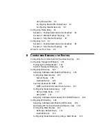
Page 10: ...dging 101 Managing the Bridge Router 102 Per Port Transparent Bridging 102 Configuring IP Routing 102 Assigning Addresses and Enabling IP Routing 103 Configuring Static Routes 103 Subnet Masks 105 Ove...

Page 11: ...14 Editing an Existing Phone Number 114 Deleting a Phone Number 114 Using Statistics on the 56 64 Kbps CSU DSU Port 45x and 55x 115 Using Statistics on the T1 FT1 RJ 48 Telco Port 46x and 56x 116 Netw...

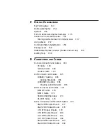
Page 12: ...rt 45x and 55x 137 Performing a Remote Loopback Test on a 56 64 Kbps CSU DSU Module 139 Performing a Local Loopback Test on the T1 FT1 Port 46x and 56x 141 Performing a Remote Loopback for V 54 on a T...

Page 13: ...nnector and Cables 163 PC Cable 163 Terminal Cable 164 Modem Cable 164 LAN Connector and Cables 165 10BASE T Cabling 165 Cabling Standards 166 100BASE TX Cabling 166 Creating a Valid Network 166 WAN C...

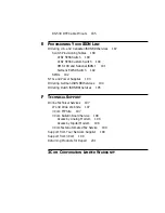
Page 14: ...92 NT1s and Power Supplies 193 Ordering German ISDN BRI Services 194 Ordering Dutch ISDN BRI Services 195 F TECHNICAL SUPPORT Online Technical Services 197 World Wide Web Site 197 3Com FTP Site 197 3C...

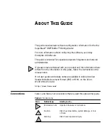
Page 15: ...information there differs from the information in this guide follow the instructions in the release notes Most user guides and release notes are available in Adobe Acrobat Reader Portable Document Fo...

Page 16: ...mple To remove the IP address enter SETDefault 0 IP NETaddr 0 0 0 0 This guide always gives the full form of a command in uppercase and lowercase letters However you can abbreviate commands by enterin...

Page 17: ...LAN ports that can be used with 10BASE T or 100BASE TX Ethernet Boundary routers model 4xx only One active Ethernet port If you upgrade to full router software the second port will be functional WAN...

Page 18: ...174 for information about Flex WAN cables Boundary routers model 4xx only One active serial or WAN port The remaining two ports can be used for back up Table 3 Features of the SuperStack II NETBuilde...

Page 19: ...button Run Load and Test LEDs Aux and Fwd LEDs Status LEDs Power Fault LED SERIAL B Console CSU DSU B1 Link Line Act Line Error WAN B2 SuperStack II NETBuilder Status Run Load Test 100Mb Link Fault A...

Page 20: ...ted on the left side of the bridge router when facing the front panel It is recessed into an opening near the DIP switches Press the switch with a nonconductive object such as a plastic stylus to acti...

Page 21: ...h level data link control HDLC with NRZ CRN command 8 data bits N no parity and 1 stop bit if a parity option is provided V 25bis addressed mode Synchronous data and DTE connection The SuperStack II N...

Page 22: ...22 CHAPTER 1 FEATURES AND SPECIFICATIONS...

Page 23: ...64 Kbps Carrier Service Unit Data Service Unit CSU DSU models 45x and 55x or T1 FT1 Telco port models 46x and 56x You can change any model 4xx bridge router to another model 4xx or any model 5xx to an...

Page 24: ...service provider Order ISDN lines from the phone company See Appendix E for more information about ordering ISDN lines Installations in Hong Kong should be configured to originate and receive ISDN cal...

Page 25: ...clude dial up lines leased lines and packet switched services Dial up lines like ISDN allow you to dial your destination when necessary and hang up when you no longer need the connection A leased line...

Page 26: ...etwork Services You can use packet switched services with your bridge router instead of dial up or leased lines to take advantage of high performance for a reasonable price This section describes X 25...

Page 27: ...to transfer the data to its destination Frame Relay differs from X 25 which was developed to work over voice grade telephone lines because it was designed to make use of today s higher speed digital l...

Page 28: ...28 CHAPTER 2 USING THE BRIDGE ROUTER IN YOUR NETWORK...

Page 29: ...CSU DSU loopback plug Rack mount kit Models 46x and 56x RJ 48 T1 cable Software CD ROM except for boundary router models Documentation and documentation CD ROM What you need to provide Synchronous ser...

Page 30: ...of the SuperStack II bridge routers Table 7 Environmental Requirements Parameter Minimum Requirement Maximum Requirement Temperature Operating 5 C 40 C Nonoperating 40 C 75 C Altitude Operating 15 00...

Page 31: ...ounting kit contains the following hardware Figure 4 Mounting Kit Contents Installing on a Tabletop If you plan to install your bridge router on a tabletop attach the rubber feet as shown Two brackets...

Page 32: ...curely stack several bridge routers on a tabletop CAUTION Do not restrict air flow around the sides and back of the bridge router Figure 5 Stacking Bridge Routers Bottom bracket acts as a support Atta...

Page 33: ...ck mount brackets to each side of the chassis using two flathead screws per bracket 2 Hold the chassis between the poles of the rack and attach the brackets to the rack using panhead screws you must p...

Page 34: ...s can use only one Ethernet port and only one serial or WAN port can be active at a time You can cable the remaining serial or WAN ports to be used as back up If you upgrade to full router software th...

Page 35: ...outlet In other countries you do not need to provide an NT1 because the function is provided by the ISDN equipment at the customer site For more information on ISDN cables see ISDN S T Cable on page 1...

Page 36: ...64K CSU DSU Models 45x and 55x bridge routers have a 56 64K CSU DSU connector The 56 64K CSU DSU port uses an RJ 48S connector For more information on CSU DSU cables see 56 64K CSU DSU Cable on page...

Page 37: ...cable from 3Com for your serial device See Serial Connectors and Flex WAN Cables on page 174 for more information about the Flex WAN cables A A Link Active Fault B SERIAL B Flex WAN cables Connect to...

Page 38: ...router reboots To reset a bridge router in this configuration turn the power off wait 5 seconds and turn it back on The bridge router switches to the RPS then switches back to the internal supply to r...

Page 39: ...modem type cable For the modem use a 9 pin female to 25 pin male straight through type cable 2 Connect one end of the cable to the console port on the SuperStack II system and the other end to the ser...

Page 40: ...40 CHAPTER 3 INSTALLING THE HARDWARE...

Page 41: ...eps 1 Remove the power cord and all cables from the chassis 2 If the bridge router is mounted with brackets unmount it and remove the brackets 3 Remove the two screws from the back of the chassis Mode...

Page 42: ...42 CHAPTER 4 INSTALLING OR REMOVING AN INTERFACE MODULE 4 Remove the cover Lift cover away from chassis With the front panel facing you push down on cover with both hands Slide cover back slightly...

Page 43: ...Existing Module Model 4xx To remove an existing module from a model 4xx bridge router follow these steps 1 Remove the screw from the standoff 2 Remove the module Rear panel Front panel Remove screw Fr...

Page 44: ...and the cover screws CAUTION The DIP switches should all be in the down position The DIP switches are accessible through an opening on the side of the chassis 5 If the bridge router was mounted with b...

Page 45: ...odel 4xx To install a new module in a model 4xx bridge router follow these steps 1 Remove the screw from the standoff if necessary 2 Move the jumper to the right hand set of pins Remove screw Front pa...

Page 46: ...all be in the down position The DIP switches are accessible through an opening on the side of the chassis 6 If the bridge router was mounted with brackets reinstall the brackets and remount it 7 Recon...

Page 47: ...Existing Module Model 5xx To remove an existing module from a model 5xx bridge router follow these steps 1 Remove the screw from the standoff 2 Remove the module Rear panel Front panel Remove screw Fr...

Page 48: ...and the cover screws CAUTION The DIP switches should all be in the down position The DIP switches are accessible through an opening on the side of the chassis 5 If the bridge router was mounted with b...

Page 49: ...ew Module Model 5xx 49 Installing a New Module Model 5xx To install a new module in a model 5xx bridge router follow these steps 1 Remove the screw from the standoff if necessary Rear panel Front pane...

Page 50: ...NTERFACE MODULE 2 Move the jumper to the right hand set of pins 3 Insert the new module Front panel Move the jumper to the right hand set of pins Front panel Connectors Connectors on underside of modu...

Page 51: ...N The DIP switches should all be in the down position The DIP switches are accessible through an opening on the side of the chassis 6 If the bridge router was mounted with brackets reinstall the brack...

Page 52: ...52 CHAPTER 4 INSTALLING OR REMOVING AN INTERFACE MODULE...

Page 53: ...section see Reference for Enterprise OS Software Turning on the System To start up your bridge router plug one end of the power cord into the rear panel of the bridge router and the other end into yo...

Page 54: ...dix A for more information If the bridge router is configured for an ETSI switch and there are no ISDN B channel connections the ISDN Line Act LED is off If a B channel is not connected the Link and C...

Page 55: ...ual that came with your Telnet application Use Simple Network Management Protocol SNMP to view and configure a subset of the parameters from a remote host For information on preparing the bridge route...

Page 56: ...command line and rules for entering commands see Appendix C To access the command line see Using the Command line Interface on page 57 The syntax for each command and parameter is described in Referen...

Page 57: ...r entering commands and using aliases and history substitution see Using Aliases on page 157 and Command History Substitution on page 158 5 To escape out of a menu press the Return key which takes you...

Page 58: ...not be specified as part of the command For more information see Entering Service Names in Command Lines on page 157 The parameter is the object of the action of the command If two or more services h...

Page 59: ...n as root with the User password you have User privilege You might log on with the User password if you do not want to create user accounts If you want to change the privilege level without logging of...

Page 60: ...bridge router resets the new baud rate is used and you will not be able to access the system software to enter any commands at the default 9600 baud rate 5 After you change the terminal baud rate rese...

Page 61: ...n and contact follow these steps 1 Required Assign a name to the bridge router using SETDefault SYS SysNAMe string For example to set the system name to Engineering SanJose enter SETDefault SYS SysNAM...

Page 62: ...vice parameter modifies the list of communities For information on how to use the COMmunity parameter see Reference for Enterprise OS Software To implement auto startup many NETBuilder configuration f...

Page 63: ...ween paths and ports is that the path is the physical interface and the port is the logical interface in the software that is mapped to the physical path Figure 6 illustrates the relationship between...

Page 64: ...ind a path from its port by using SETDefault path PATH DialCONTrol DYNamic See Configuring Bandwidth Management for PPP on page 89 for more information about bandwidth management features such as dial...

Page 65: ...l port functions the same way as a nonvirtual port does that is as a logical interface that represents a connection to a network For example if a SuperStack II bridge router central node needs to conn...

Page 66: ...RIP IPX and AppleTalk RTMP allows communication between bridge routers that are not directly connected to one another To configure next hop split horizon for these routing protocols you must have a li...

Page 67: ...ibutes of the path over which they are defined PPP virtual ports can be used with dial up related parameters Frame Relay and X 25 virtual ports cannot be used with dial up related parameters You can u...

Page 68: ...se the path was unbound from its port and placed into the dynamic dial path pool Unlike Frame Relay and X 25 virtual ports which are always associated with a particular path PPP virtual ports can pote...

Page 69: ...No Mapped To 1 L1 1 2 L2 2 3 1 For built in ISDN ports the path numbering convention differs from the convention on a non ISDN port Instead of numbering only the physical interface or connector such a...

Page 70: ...the following configuration procedures Configuring ISDN in the U S and Canada Configuring ISDN in Europe Australia and Asia Configuring ISDN in the U S and Canada Before beginning this procedure compl...

Page 71: ...ge router If the SpidWIZard parameter does not detect the switch type and SPIDs correctly complete the procedure in the next section Configuring ISDN in Europe Australia and Asia Before beginning this...

Page 72: ...hannel B2 as a separate line and your telecommunications carrier provided only one telephone number for all channels specify a subaddress using SETDefault 3 2 PATH LocalSubAddr string 5 Enable both ch...

Page 73: ...the phone number 453 4444 enter ADD 2 POrt DialNoList 4534444 Type BriV Enabling Digi64S2 There are two types of ISDN leased lines in Germany Digi64S and Digi64S2 Digi64S can run only on the B1 channe...

Page 74: ...T1 RJ 48 Telco Port Model 46x and 56x This section describes how to configure the T1 FT1 RJ 48 Telco port Before beginning this procedure complete the following tasks Cable the T1 FT1 RJ 48 Telco port...

Page 75: ...it 7 zero code substitution AMIB7ZCS Configuring Serial Ports with DCEs This section describes how to configure the serial ports with modems CSU DSUs or ISDN TAs attached Before beginning this procedu...

Page 76: ...fault path PATH CONTrol Enabled Configuring Serial Ports with DTEs This section describes how to configure the serial ports when connecting directly to IBM legacy equipment Before beginning this proce...

Page 77: ...From Here 77 Where to Go From Here If you have a leased line see Chapter 8 to configure bridging IP and IPX routing For dial up Frame Relay or X 25 lines see Chapter 7 to complete your port and path c...

Page 78: ...78 CHAPTER 6 BASIC CONFIGURATION OF PORTS AND PATHS...

Page 79: ...on all models Bandwidth management features that can be enabled after configuring the ports and paths are described in Table 17 Table 17 Bandwidth Management Features for Dial Up Lines Bandwidth Mana...

Page 80: ...The dial number list is required Procedure included in scenarios More information See Chapter 9 Bandwidth on demand When the system detects traffic congestion on a port you can enable bandwidth on dem...

Page 81: ...s on the same bridge router Start here Done B1 64 K B2 64 K 1 510 555 1234 Create the dial number list for ports 3 and 4 ADD 3 PORT DialNoList 1 408 555 1000 Baud 64 Type Bri ADD 4 PORT DialNoList 1 5...

Page 82: ...dial number list for port 3 If you have one phone number for your destination enter the number twice with a letter after the second entry If you have two numbers enter each phone number ADD 3 PORT Dia...

Page 83: ...l pool 1 510 555 1234 1 408 555 1000 Saratoga Berkeley NETBuilder II 128 K 64 K 1 415 555 2000 B1 1 415 555 2001 B2 LosAltos NETBuild er Router CONNEC T O F F I C E System WAN ISDN LAN Line Act Line E...

Page 84: ...Description The call to Saratoga is complete The local bridge router then dials Berkeley using the first available path 128 K 64 K 3 2 path 4 path 3 1 path B1 64 K B2 64 K TA 64 K 1 510 555 1234 1 40...

Page 85: ...e number ADD V1 PORT DialNoList 1 408 555 1000 Baud 64 Type Bri ADD V1 PORT DialNoList 1 408 555 1000a Baud 64 Type Bri ADD V2 PORT DialNoList 1 510 555 1234 Baud 64 Type Bri ADD V3 PORT DialNoList 1...

Page 86: ...Destination per Port This scenario shows a model 44x bridge router connecting to one destination on each serial port Start here Done 128 K 28 8 K 1 510 555 9876 Create the dial number list for ports 5...

Page 87: ...th PPP on page 79 for information about using the built in ISDN port and a TA in a dial pool The dial pool does not have to contain both serial paths You can use one path in the dial pool to connect t...

Page 88: ...irst available 19 2 Kbps path 4 path 3 path modem 28 8 K modem 19 2 K 1 619 555 2222 1 650 555 6969 1 609 555 6000 Princeton Andover NETBuilder II 28 8 K 19 2 K PaloAlto NETBuild er Router CONNEC T O...

Page 89: ...bandwidth for each virtual port SETDefault V1 PORT NORMalBandwidth 28 8 SETDefault V2 PORT NORMalBandwidth 19 2 SETDefault V3 PORT NORMalBandwidth 28 8 Create the dial number list for each virtual po...

Page 90: ...the following numbers in succession if required The dial number list allows you to use a different path for each phone number by specifying the baud rate and device type For example the first number...

Page 91: ...he list then the following numbers in succession if required See Working with Dial Number Lists on page 113 for more information about dial number lists To configure bandwidth on demand follow these s...

Page 92: ...onal dial path is activated The additional dial path is deactivated when the rate of traffic is less than 28 8 kbps for longer than 60 seconds Configuring Disaster Recovery If the primary PPP line fai...

Page 93: ...OS Software for configuration procedures Obtain DLCIs for each remote site from the Frame Relay service provider A DLCI identifies a circuit from the bridge router to a destination The destination use...

Page 94: ...dge routers create virtual ports for each remote site on the central site so traffic can pass from one remote site to another over the same parent port 6 port CSU DSU Frame Relay CSU DSU CSU DSU V1 V2...

Page 95: ...hop split horizon feature in the routing protocol See Using Enterprise OS Software for more information In this scenario site B is not connected to site C and site A is not connected to site D Create...

Page 96: ...tualPort 3 90 ADD V2 PORT VirtualPort 3 100 One serial port connects to multiple destinations in a partially meshed topology ADD port PORT VirtualPort path DLCI Syntax Site A Start here Done Create a...

Page 97: ...from the service provider No configuration is required for this scenario Configuring X 25 This section describes two X 25 scenarios Scenario 1 Multiple Destinations Nonmeshed Scenario 2 Fully Meshed T...

Page 98: ...art here Done If you are attached to a public data network PDN specify the type SETDefault 6 X25 PDNetworkType TELENET TYMNET PSS DDN BFE NET2 DATEX TRANSPAC LAPOSTE One serial port connects to multip...

Page 99: ...dem 5 path 311041501111 311041504444 311041502222 311041503333 Start here Done If you are attached to a public data network PDN specify the type SETDefault 6 X25 PDNetworkType TELENET TYMNET PSS DDN B...

Page 100: ...100 CHAPTER 7 ADVANCED CONFIGURATION OF PORTS AND PATHS...

Page 101: ...t support leaf node Boundary Routing Boundary Routing system architecture treats the remote site as another central site LAN segment which allows all routing to occur at the central site Boundary rout...

Page 102: ...ing This section contains the following information Assigning Addresses and Enabling IP Routing Configuring Static Routes Learning Routes with OSPF Configuring Route Redundancy Assigning Addresses Aut...

Page 103: ...work management and stops routing IP packets Do not configure an IP address for port 0 if you want to route IP packets 2 Enable IP routing by entering SETDefault IP CONTrol ROute Configuring Static Ro...

Page 104: ...10 0 0 0 11 0 0 1 1 This example shows that network number 10 0 0 0 the Los Angeles network is reachable by router 1 through gateway 11 0 0 1 on router 2 The gateway address is the IP address of port...

Page 105: ...ng a mask by entering ADD IP ROUte 130 10 112 0 255 255 255 0 130 10 109 5 3 Router 2 Router 3 First floor Third floor Router 1 Host IP address 130 10 108 6 Subnet mask 255 255 255 0 Second floor 1 3...

Page 106: ...verride Learning Routes with OSPF OSPF is a dynamic routing protocol that creates routing tables automatically For information about other dynamic routing protocols like RIP see Using Enterprise OS So...

Page 107: ...ssible because topology changes bring up the interface Configuring Route Redundancy By configuring route redundancy you can use a back up line to route traffic if your primary line fails To configure...

Page 108: ...configured For more information or if you are unsure if an Internet address has been assigned contact the network administrator at the central site or your network supplier Internet addresses are ass...

Page 109: ...ines Disable WAN broadcasts to reduce traffic on your dial on demand dial up lines using SETDefault port IPX CONTrol NoWanBcast NoWanBcast causes the IPX router to drop WAN broadcast packets to preven...

Page 110: ...default route using ADD port IPX ROUte Default media address hops Override Option If a destination network is reachable with both a static route and a learned route the router uses the static route un...

Page 111: ...to port 1 enter SETDefault 1 PATH NAme Floor_1 SETDefault 1 PORT NAme Bldg_1 Path and Port Naming Restrictions The following restrictions exist for the PATH and PORT NAme parameter The name string can...

Page 112: ...orrect baud rate Defaults The default setting is Autobaud ON You can turn off autobaud by setting the baud rate For example to set the baud rate to 64 K enter SETDefault 2 PAth BAud 64 The autobaud fe...

Page 113: ...e second number is used for a 64 Kbps ISDN line You can use hyphens in your phone number For ISDN the phone number includes a dial prefix country code and area code and possibly a subaddress If you sp...

Page 114: ...can insert the same phone number twice by using blanks or other redundant characters You also can include the Baud and Type keywords in any order when inserting phone numbers into the dial number lis...

Page 115: ...00 45 01 00 01 15 01 30 01 45 02 00 02 00 SevErrSecs 00000 00000 00000 00000 00000 00000 00000 00000 00000 ErrSecs 00000 00000 00000 00000 00000 00000 00000 00000 00000 ErrFreeSecs 00000 00000 00000...

Page 116: ...10 EFS 00245M 00 15 00 30 00 45 01 00 01 15 01 30 01 45 02 00 02 00 ES 00000 00000 00000 00000 00000 00000 00000 00000 00000 SES 00000 00000 00000 00000 00000 00000 00000 00000 00000 UAS 00900 00900 0...

Page 117: ...00 00000 00000 00000 UAS 00900 00900 00900 00900 00900 00900 00900 00900 00900 BES 00900 00900 00900 00900 00900 00900 00900 00900 00900 CSS 00900 00000 00000 00000 00000 00000 00000 00000 00000 LOFC...

Page 118: ...the following appears EFS Error counter 100 Signal State AVAILABLE RLOS No RLOF No RAIS No RMYEL No RYEL No TYEL No Remote Inband Lpbck Disabled Time in current interval 100 Current Interval ES 00005...

Page 119: ...ams A display similar to the following appears Path 2 T1FrameMode ESF Path 2 T1LineCoding B8ZS Path 2 T1LineDistance LH1 0db Path 2 T1DS0ChnlBaud FT164K Path 2 T1ChannelMap 1 2 3 4 5 6 7 8 9 10 11 Con...

Page 120: ...120 CHAPTER 9 CUSTOMIZING YOUR SOFTWARE...

Page 121: ...The monitor utility stops the software from running and you must reset the bridge router to exit the firmware The following commands are available from the monitor utility Boot Syntax BT filename con...

Page 122: ...ename 6 Port Selection 7 Baud Rate 8 Duplex Mode Clear EEPROM Syntax CP Description The CP command erases the EEPROM except for the MAC address You should only do this if advised by 3Com technical sup...

Page 123: ...gured addressing in the CL command you must not include the filename Help Syntax H or Description The Help command lists all available commands in the boot monitor along with syntax parameters Repeat...

Page 124: ...ndicate system is running self tests Provides additional status for the Run Load and Test LEDs Lights green when unit has power Lights amber if there is a problem with power When unlit power to unit i...

Page 125: ...n error in the frames is detected Lights green when an end to end connection exists or is in progress Connect Fault CSU DSU B1 Link Line Act Line Error WAN B2 Connect Fault CSU DSU B1 Link B2 Line Act...

Page 126: ...urred during the system software load phase Compare your System LEDs with the following examples and follow the instructions for troubleshooting Meaning The file system is empty Action Reload the soft...

Page 127: ...the image has been deleted reload the software using Appendix B 3 If the image has a different name or is in a different directory boot from the image using BT path filename Meaning File too large Ac...

Page 128: ...he software See Appendix B Meaning File checksum error Action Reload the software See Appendix B Meaning Unspecified fatal error Action Reload the software See Appendix B SYSTEM Status Run Test Power...

Page 129: ...t or is incorrectly configured Action Check Trivial File Transfer Protocol TFTP BOOTP server configuration and verify the media access control MAC address of the bridge router Turn the power off and t...

Page 130: ...oad If the load is unsuccessful contact your network supplier for assistance Meaning No response to TFTP request The TFTP server is not present the incorrect file was downloaded or the file is incorre...

Page 131: ...urred during the system test phase Meaning EEPROM checksum test failed Action Contact your network supplier Errors Indicated by the Serial LEDs If the Fault LED in the serial LED section of your bridg...

Page 132: ...r CSU DSU connections Meaning Indicates a loss of signal possibly due to a disconnected cable Action Check all cable connections Meaning An error in received frames has been detected on either channel...

Page 133: ...e bridge router displays Path x Detected DTE Loopback OFF switching to normal mode Performing a Loopback Test on the ISDN Port 43x 53x 44x and 54x This section describes how to perform a loopback test...

Page 134: ...ish a connection between the two B channels by dialing out on one channel and dialing into the other using DIal path To dial path 3 1 from path 3 2 enter DIal 3 2 Path 3 2 places a call to the number...

Page 135: ...nd the number of errors using DLTest Stat 9 Stop the DLTest by entering DLTest Abort 10 Disconnect the call by entering HangUp 3 2 11 Change the port owner from loopback to PPP by entering SETDefault...

Page 136: ...sage is displayed V 54 data loopback succeeded If the destination device does not respond the following message is displayed V 54 local loopback terminated remote site not responding If the data is co...

Page 137: ...ows the data flow that occurs when this loopback test is performed Figure 11 CSU DSU Local Loopback Testing Before running the CSU DSU loopback test attach a console or Telnet to your bridge router To...

Page 138: ...packets equals or approximately equals the number of transmitted packets your line has passed the loopback test If your line does not pass the test verify that the software is configured correctly Als...

Page 139: ...ber of the port you are testing The remote loopback test includes remote CSU Loopback and remote DSU Loopback To perform a remote loopback test follow these steps 1 Set the baud rate of the port The d...

Page 140: ...er RemtLpbck 3 PAth RemtCsuLbkStart To start the remote DSU loopback test on path 2 enter RemtLpbck 3 PAth RemtDsuLbkStart 4 To view the status of the loopback test in progress enter RemtLpBck 3 PAth...

Page 141: ...the loopback plug that came with your system 2 Disable the WAN path by entering SETDefault 3 PATH CONTrol Disable 3 Set the owner of the WAN port to loopback by entering SETDefault 3 PORT OWNer LoopBa...

Page 142: ...Disable 2 Enable V 54 signal detection by entering LPBCK 3 PATH V54LpbckYes 3 Start the loopback test by entering LPBCK 3 PATH V54LpbckSTART 4 Stop the loopback test by entering LPBCK 3 PATH V54Lpbck...

Page 143: ...RT for a payload loopback test LPBCK 3 PATH V54LpbckSTART 3 To stop the loopback test enter LPBCK 3 PATH RmANSILnLpbckSTOP for a line loopback test or LPBCK 3 PATH RmANSIPyldLpbckSTOP for a payload lo...

Page 144: ...erial port you are testing by referring to Table 14 or Table 15 on page 69 To perform a loopback test on the serial port follow these steps 1 Set the line type to Leased using SETDefault path PATH Lin...

Page 145: ...Dump If a SuperStack II bridge router unexpectedly stops functioning it performs a memory dump A memory dump provides a view of the internal state of the system which can help Technical Support deter...

Page 146: ...from the System Configuration menu The default parameters are shown in bold 4 Select Dump Destination The following options are available 1 No Full Dump 2 Network 5 If you select No Full Dump the sys...

Page 147: ...iated 10 Type Q repeatedly to exit the System Configuration menus and return to the Enterprise OS prompt Obtaining the MAC Address You need to obtain the media access control MAC address of the SuperS...

Page 148: ...on if you have any problems Verifying the TFTP Process To verify that a TFTP transfer can occur from the SuperStack II bridge router to the TFTP server follow these steps 1 Obtain a listing of the fil...

Page 149: ...Status word 0x0015 Instruction 0x1012 PC 0x4A2244 Dumping memory to network Dumping to file Trying AUI port No Carrier on AUI port trying 10BaseT port carrier detected TFTP write of file to server 139...

Page 150: ...150 APPENDIX A TROUBLESHOOTING...

Page 151: ...ress of the server Transfers the boot 68k file from the server Creates the primary directory Places the image in the primary directory Reloading the Software You must have a console attached to your S...

Page 152: ...r FL path boot 68k If you are using a TFTP BOOTP server enter FL The FL command formats the flash memory and uses TFTP to copy the image from the identified server to the flash drive If you are using...

Page 153: ...symbols see Symbols on page 154 Figure 15 Full Form Syntax SETDefault port BRidge TransparentBRidge TransparentBRidge NoTransparentBRidge A hyphen always precedes service name and must be entered if t...

Page 154: ...abbreviation of a command service name or parameter Parameter name Value Table 18 Command Syntax Symbols Symbol Description angle brackets Enclose a variable or value You must specify the variable or...

Page 155: ...iple authorities GENSER SIOP SCI NSA DOE NONE when entering the command hyphen A letter preceded by a hyphen represents a command option Also when you enter a service name as part of the command you m...

Page 156: ...T RO F SEC For consistency and clarity in the Enteprise OS and NETBuilder family guides the full form syntax is provided However you can use the abbreviated form by only typing the uppercase portion o...

Page 157: ...ices parameter If multiple services are set the system prompt is displayed For information on using the CurrentServices parameter see Reference for Enterprise OS Software If the command is for a Globa...

Page 158: ...at starts with string The SHow History command might display the following commands 166 setdefault 1 path control enabled 167 show path configuration 168 show history 169 set screenlength 23 170 setde...

Page 159: ...N path When using an ISDN TA connected to a serial port both B channels are assigned the same path number You do not need to use special ISDN syntax The syntax variation for these parameters is presen...

Page 160: ...point then an asterisk for example 3 A path is the physical interface that connects the bridge router to a physical medium such as an Ethernet bus a token ring or a serial line In an ISDN environment...

Page 161: ...st of PORT Service parameters that can be used with the SETDefault command enter the following command SETDefault PORT command Displays the parameters by service name that can be used with the selecte...

Page 162: ...162 APPENDIX C SYNTAX CONVENTIONS...

Page 163: ...tors with metallic backshells PC Cable Figure 17 shows the pinouts for a 9 pin female to 9 pin null modem type cable Figure 17 9 pin to 9 pin PC Cable Null Modem Type 5 4 3 2 1 9 8 7 6 5 4 3 2 1 9 8 7...

Page 164: ...GND DTR DSR Transmit Data Receive Data Request to Send Clear to Send Carrier Detect Signal Ground Data Set Ready Data Terminal Ready Receive Data Transmit Data Carrier Detect Clear to Send Request to...

Page 165: ...20 Ethernet Connector 10BASE T Cabling Table 21 lists supported 10BASE T cable types and emissions classes 1 2 3 4 5 7 8 6 TX RX TX RJ 45 female shielded RX Table 21 10BASE T Cable Types and Emission...

Page 166: ...or better UTP or shielded UTP T4 does not connect to the SuperStack II NETBuilder SI bridge router but you can use T4 in your network between appropriate devices Follow the steps in the next section t...

Page 167: ...omain diameter follow these steps 1 Determine which interfaces will be used TX FX or T4 2 Add up the combined length of all cabling to be used 3 Determine which class of repeaters if any are used in t...

Page 168: ...he IEEE Standard 802 3 Figure 22 Collision Domain Diameter with No Repeater Figure 23 Collision Domain Diameter with One Repeater DTE device SuperStack II NETBuilder DTE device SuperStack II NETBuilde...

Page 169: ...LAN Connector and Cables 169 Figure 24 Collision Domain Diameter with Two Repeaters Fast Ethernet Repeater Fast Ethernet Repeater DTE device DTE device SuperStack II NETBuilder...

Page 170: ...r see Figure 23 200 m 100 m max on each side of the repeater 272 m 260 8 m 100 m max TX Remaining length of FX 231 m 100 m max T4 Remaining length of FX One Class 2 repeater see Figure 23 200 m 100 m...

Page 171: ...8 6 RJ 45 male shielded 1 2 3 4 5 7 8 6 Name Abbr Pin Pin Abbr Name 1 2 3 4 5 6 7 8 1 2 3 4 5 6 7 8 NC NC TxD RxD RxD TxD NC NC NC NC TxD RxD RxD TxD NC NC Not connected Not connected Transmit Data R...

Page 172: ...l This cable comes with your bridge router Figure 26 shows the pinouts of the ISDN U cable Figure 26 ISDN U Cable RJ 45 male shielded To WAN port To wall outlet 1 2 3 4 5 7 8 6 RJ 11 male shielded 12...

Page 173: ...48S male shielded To WAN port To wall outlet 1 2 3 4 5 7 8 6 RJ 48S male shielded 1 2 3 4 5 7 8 6 Name Abbr Pin Pin Abbr Name 1 2 3 4 5 6 7 8 1 2 3 4 5 6 7 8 R1 T1 NC NC NC NC T R R1 T1 NC NC NC NC T...

Page 174: ...ted to DTE and DCE devices with the following interfaces RS 232 V 35 X 21 RS 449 RS 530 DCE only RJ 48S male shielded To WAN port To wall outlet 1 2 3 4 5 7 8 6 RJ 48S male shielded 1 2 3 4 5 7 8 6 Na...

Page 175: ...lex WAN DCE cable The DCE cable has a DCE connector on the end that connects to the mainframe see Figure 29 Figure 29 Connecting the Bridge Router to a DTE Using a DCE Cable To connect the bridge rout...

Page 176: ...0018 page 184 V 35 extended shroud DTE straight through cable to connect to a DCE 3C890020 page 179 V 35 extended shroud DCE crossover cable to connect to a DTE 3C89022 page 180 10 ft RS 232 DTE strai...

Page 177: ...DCD 1 DSR DTR 34 6 DSR 2 CTS RTS 35 5 CTS 3 RxD TxD 36 3 RxD 4 TxC Nil 37 15 TxC 5 RxC TxCE 38 17 RxC 6 TxCE TxC 39 24 TxCE 7 TxD RxD 41 2 TxD 8 RTS CTS 42 4 RTS 9 DTR DSR 43 20 DTR 10 LL DCD 44 18 L...

Page 178: ...LTST 1 DSR DTR 34 20 DTR 2 CTS RTS 35 4 RTS 3 RxD TxD 36 2 TxD 4 RxC TxCE 38 24 TxCE 5 TxCE TxC 39 15 TxC 6 Nil RxC 40 17 RxC 7 TxD RxD 41 3 RxD 8 RTS CTS 42 5 CTS 9 DTR DSR 43 6 DSR 10 LL DCD 44 8 DC...

Page 179: ...3 AA SCT 3 TxC RxC 24 Y SCT RxC TxCE 25 X SCR 4 RxC TxCE 26 V SCR RxD TxD 27 T RD 5 RxD TxD 28 R RD DCD LL 33 F RLSD 6 DSR DTR 34 E DSR 7 CTS RTS 35 D CTS 8 RTS CTS 42 C RTS 9 DTR DSR 43 H DTR 10 LL D...

Page 180: ...20 Y SCT Nil SCR 21 X SCR 3 Nil SCR 22 V SCR RxC TxCE 25 W SCTE 4 RxC TxCE 26 U SCTE RxD TxD 27 S SD 5 RxD TxD 28 P SD DCD LL 33 K LT 6 DSR DTR 34 H DTR 7 CTS RTS 35 D RTS 8 RTS CTS 42 C CTS 9 DTR DSR...

Page 181: ...CTS RTS 2 12 Indicate RTS CTS 9 3 Control 2 RTS CTS 10 10 Control TxD RxD 11 2 Transmit 3 TxD RxD 12 9 Transmit Circuit Ground 15 8 Control GND 4 RxC TxCE 25 13 Timing 5 RxC TxCE 26 6 Timing RxD TxD...

Page 182: ...ontrol 1 CTS RTS 2 2 Control RTS CTS 9 5 Indicate 2 RTS CTS 10 12 Indicate TxD RxD 11 4 Receive 3 TxD RxD 12 11 Receive Circuit Ground 15 8 Control GND 4 TxC RxC 23 13 Timing 5 TxC RxC 24 6 Timing RxD...

Page 183: ...7 RS 5 RTS CTS 10 25 RS TxD RxD 11 25 SD 6 TxD RxD 12 4 SD TxCE TxC 13 17 TT 7 TxCE TxC 14 35 TT Circuit Ground 15 19 SGRC 8 Circuit Ground 16 20 SGRC TxC RxC 23 23 ST 9 TxC RxC 24 5 ST RxC TxCE 25 26...

Page 184: ...le Pinouts Flex WAN Connector RS 449 DCE Connector Signal Pin Direction Pin Signal Twisted Pair CTS RTS 1 7 RS 1 CTS RTS 2 25 RS DSR DTR 3 12 TR 2 DSR DTR 4 30 TR DCD DCD 5 13 RR 3 DCD DCD 5 31 RR DTR...

Page 185: ...l LL 29 10 LLSC 12 Circuit Ground 30 37 Ground Shield Ground 46 Cable Shield 1 Shield Ground Shorting Group 1 48 49 Table 32 RS 449 DCE Cable Pinouts continued Flex WAN Connector RS 449 DCE Connector...

Page 186: ...DCD DCD 5 8 DCD DCD DCD 5 10 DCD DTR DSR 7 20 DTR DTR DSR 8 23 DTR RTS CTS 9 4 RTS RTS CTS 10 19 RTS TxD RxD 11 2 TxD TxD RxD 12 14 TxD TxCE TxC 13 24 TxCE TxCE TxC 14 11 TxCE TxC RxC 23 12 TxC TxC R...

Page 187: ...code IOC is Capability R The IOC tells the telephone company which parameter settings to use for SuperStack II bridge routers Not all Regional Bell Operating Companies use IOCs 4 If you have a model 4...

Page 188: ...e may not require the SPID number Your telephone company gives you the phone number and SPID number after it installs your line If your telephone company has the IOC for a SuperStack II bridge router...

Page 189: ...ormation Specification Line type National ISDN 1 line Line code 2B1Q 2B D Interface type S T interface with NT1 model 43x or U interface model 44x and RJ 45 jack Maximum terminals MAXTERM 1 Maximum B...

Page 190: ...1Q 2B D Interface type S T interface with NT1 model 43x or U interface model 44x and RJ 45 jack Maximum terminals MAXTERM 1 Maximum B channels MAXB CHNL 2 Circuit switched data CSD 2 Circuit switched...

Page 191: ...ional ISDN 1 line Line code 2B1Q 2B D Interface type S T interface with NT1 model 43x or U interface model 44x and RJ 45 jack Circuit switched option Yes Bearer Restriction option No packet mode data...

Page 192: ...h B channel the suffix can be the same A suffix of 0 is typical in this case If you decide to use the same telephone number for both B channels use a different suffix so that the two SPIDs are unique...

Page 193: ...onference because a SuperStack II bridge router does not support them NT1s and Power Supplies The models 43x and 53x bridge routers do not come with an NT1 North American telephone companies require a...

Page 194: ...Mehrger teanschlu By specifying Mehrger teanschlu you are requesting a connection for multiple types of equipment such as bridge routers telephones faxes and computers 6 Sign your name at the bottom...

Page 195: ...g from the Dutch PTT 2 Under 1 specify Nieuwe ISDN aansluiting 3 Under 3 specify the requested connection date 4 Under 4 specify Enkelvoudige ISDN 2 aansluiting 5 Under 7 specify how many phone number...

Page 196: ...196 APPENDIX E PROVISIONING YOUR ISDN LINE...

Page 197: ...ld Wide Web site 3Com FTP site 3Com Bulletin Board Service 3Com BBS 3ComFactsSM automated fax service World Wide Web Site Access the latest networking information on the 3Com Corporation World Wide We...

Page 198: ...modem to 8 data bits no parity and 1 stop bit Call the telephone number nearest you Access by Digital Modem ISDN users can dial in to the 3Com BBS using a digital modem for fast access up to 64 Kbps T...

Page 199: ...dy Product model name part number and serial number A list of system hardware and software including revision levels Diagnostic error messages Details about recent configuration changes if applicable...

Page 200: ...pe From anywhere in Europe call 31 0 30 6029900 phone 31 0 30 6029999 fax From the following European countries you may use the toll free numbers Austria Belgium Denmark Finland France Germany Hungary...

Page 201: ...iddle East 44 1442 435860 44 1442 435718 From the following European countries you may call the toll free numbers select option 2 and then option 2 Austria Belgium Denmark Finland France Germany Hunga...

Page 202: ......

Page 203: ...bandwidth on demand 91 baud Ethernet 70 serial 76 Baud parameter 76 baud rate console port configuring 60 default 60 Boot command 121 boot path 121 BOOTP server 108 151 boundary router active ports 3...

Page 204: ...ing bandwidth on demand 91 baud rate Ethernet 70 serial port 76 bridging 101 CSU DSU port 74 dial on demand 90 dial pool 82 87 dial up 79 disaster recovery 92 Frame Relay 93 IP routing 102 IPX routing...

Page 205: ...er 76 F fast Ethernet 70 Fault LED 124 LAN 125 serial 124 WAN 125 fax service 3ComFacts 199 FCC Part 68 4 CSU DSU module 4 NT1 module 4 feet attaching 31 Flex WAN See serial port For 25 Frame Relay co...

Page 206: ...25 leased 25 Link LED LAN 125 serial 124 WAN 125 LMI protocol 93 load errors 152 Load LED 124 126 LocalDialNo parameter 70 LocaSubAddr parameter 71 logging on 55 loopback plug 29 loopback testing ISDN...

Page 207: ...N 24 multiple paths per port 65 92 multiple ports per path 65 naming restrictions 111 numbering 69 parent 68 serial configuring DCEs 75 configuring DTEs 76 virtual configuring dial pool 85 89 configur...

Page 208: ...T 5ESS 189 AT T 5ESS custom 190 DMS 100 191 National 191 Siemens EWSD 192 syntax command abbreviated 154 155 full form 153 155 symbols used 154 SYS Service ALias parameter 157 RemoteManager parameter...

Page 209: ...ts configuring dial pool 85 89 configuring Frame Relay 94 95 configuring X 25 98 definition 65 inherited attributes 68 naming restrictions 111 over Frame Relay and X 25 66 PPP 67 W WAN LEDs 125 WAN po...

Page 210: ...210 INDEX...

Page 211: ...in connection or combination with the 3Com products including hardware software and firmware accurately exchange date data with the 3Com products with the exception of those products identified at 3Co...

Page 212: ......

Reviews: