


46
C
HAPTER
4: I
NSTALLING
OR
R
EMOVING
AN
I
NTERFACE
M
ODULE
3
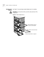
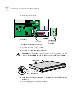
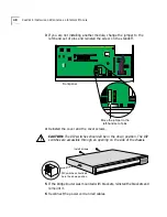
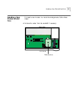
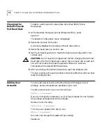
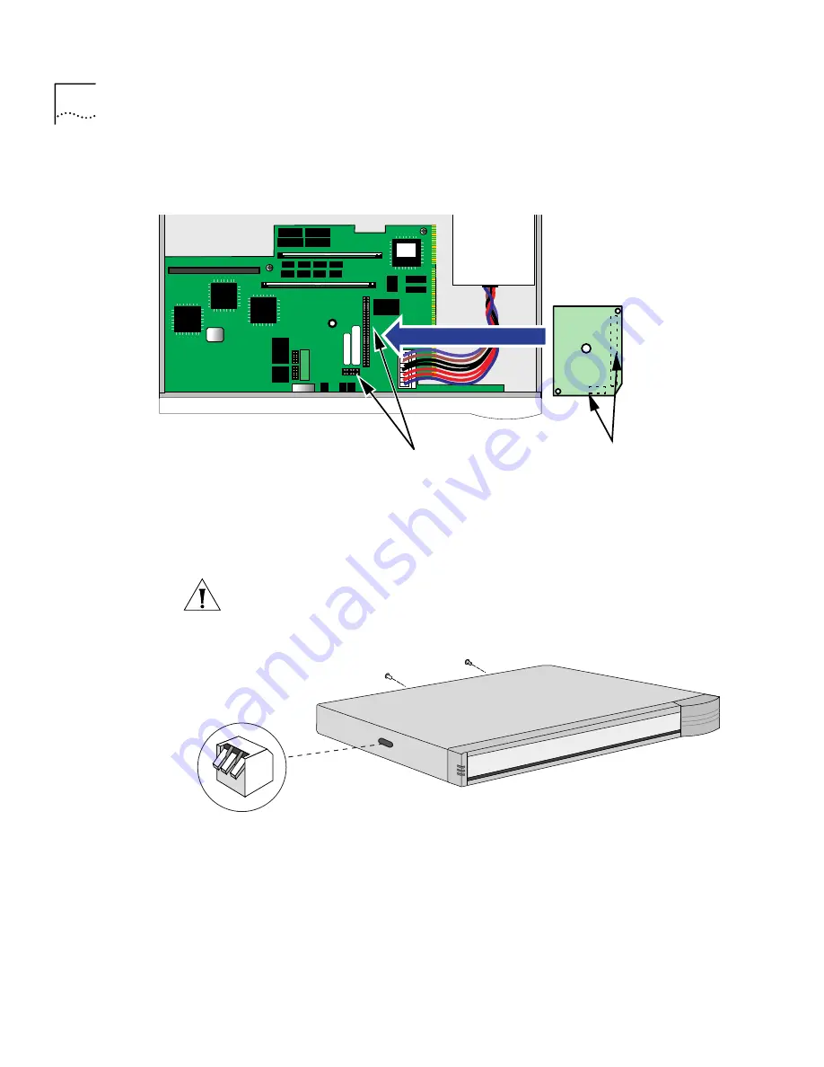
Insert the new module.
4
Reinstall the screw on the standoff.
5
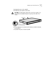
Reinstall the cover and the cover screws.
CAUTION:
The DIP switches should all be in the down position. The DIP
switches are accessible through an opening on the side of the chassis.
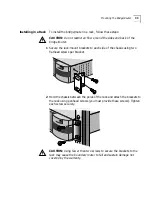
6
If the bridge/router was mounted with brackets, reinstall the brackets and
remount it.
7
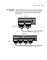
Reconnect the power cord and all cables.
Front panel
Connectors
Connectors
(on underside
of module)
Install module by matching connectors
DIP switches should all
be in the down position
Install screws
Summary of Contents for NETBuilder SI
Page 6: ......
Page 22: ...22 CHAPTER 1 FEATURES AND SPECIFICATIONS...
Page 28: ...28 CHAPTER 2 USING THE BRIDGE ROUTER IN YOUR NETWORK...
Page 40: ...40 CHAPTER 3 INSTALLING THE HARDWARE...
Page 52: ...52 CHAPTER 4 INSTALLING OR REMOVING AN INTERFACE MODULE...
Page 78: ...78 CHAPTER 6 BASIC CONFIGURATION OF PORTS AND PATHS...
Page 100: ...100 CHAPTER 7 ADVANCED CONFIGURATION OF PORTS AND PATHS...
Page 120: ...120 CHAPTER 9 CUSTOMIZING YOUR SOFTWARE...
Page 150: ...150 APPENDIX A TROUBLESHOOTING...
Page 162: ...162 APPENDIX C SYNTAX CONVENTIONS...
Page 196: ...196 APPENDIX E PROVISIONING YOUR ISDN LINE...
Page 202: ......
Page 210: ...210 INDEX...
Page 212: ......


