18
C
HAPTER
2: H
ARDWARE
I
NSTALLATION
When positioning your Access Point, ensure:
■
It is out of direct sunlight and away from sources of heat.
■
Cabling is away from power lines, fluorescent lighting fixtures, and
sources of electrical noise such as radios, transmitters and broadband
amplifiers.
■
Water or moisture cannot enter the case of the unit.
■
Air flow around the unit and through the vents in the side of the case
is not restricted. 3Com recommends you provide a minimum of
25 mm (1 in.) clearance.
Using the Rubber
Feet
Use the four self-adhesive rubber feet to prevent your Access Point from
moving around on your desk or when stacking with other flat top
OfficeConnect units. Only stick the feet to the marked areas at each
corner of the underside of your Access Point.
Wall Mounting
There are two slots on the underside of the Access Point that can be used
for wall mounting.
When wall mounting the unit, ensure that it is within reach of the power
outlet.
You will need two suitable screws to wall mount the unit. To do this:
1
Ensure that the wall you use is smooth, flat, dry and sturdy and make two
screw holes which are 150 mm (5.9 in.) apart.
2
Fix the screws into the wall, leaving their heads 3 mm (0.12 in.) clear of
the wall surface.
3
Remove any connections to the unit and locate it over the screw heads.
When in line, gently push the unit on to the wall and move it downwards
to secure.
When making connections, be careful not to push the unit up and off the
wall.
CAUTION:
Only wall mount single units, do not wall mount stacked
units.
Summary of Contents for OfficeConnect 3CRWE41196
Page 6: ......
Page 10: ...10 ABOUT THIS GUIDE ...
Page 20: ...20 CHAPTER 2 HARDWARE INSTALLATION ...
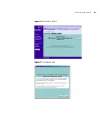
Page 25: ...Accessing the Wizard 25 Figure 10 Welcome Screen Figure 11 Wizard Screen ...
Page 68: ...68 APPENDIX C TECHNICAL SPECIFICATIONS ...
Page 87: ......


