28
C
HAPTER
2: I
NSTALLING
THE
S
WITCH
Cascade Extender Unit. The Cascade Module is installed into the
expansion slot at the rear of the Switch and the Cascade Extender Unit
plugs into the Cascade Module.
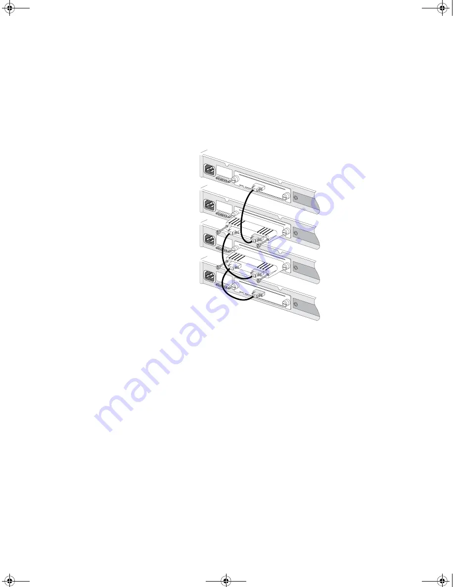
Figure 8
Stacking more than two Switch 4400 units
For information on ordering the Cascade Kits contact your supplier. For
illustrations and information on how to install the Cascade Kits, refer to
the user documentation that accompanies these Kits.
Rules For Stacking
Units
This information is also provided in the user documentation that
accompanies the Cascade Kits.
■
The maximum number of Switch units in a stack is limited to 8. The
stack may contain a combination of 24 and 48 port units.
■
Only one Cascade Module can be installed per Switch. If Cascade
Modules are fitted to both expansion slots in a Switch then both
Modules will be disabled.
■
Cascade Modules are NOT hot-swappable or hot-insertable. Ensure
that the Switch is powered off before inserting or removing a Cascade
Module.
SuperStack 3 Cascade Module
3C17224
Switch 1
SuperStack 3 Cascade Module
3C17224
UP
Switch 2
3C172
24
DOW
N
3C17224
SuperStack 3 Cascade Module
DOWN
UP
SuperStack 3 Cascade Module
3C17224
UP
Switch 4
SuperStack 3 Cascade Module
3C17224
UP
Module 2
Module 2
Switch 3
3C1722
4
DOWN
UP
Module 2
Module 2
DUA1720-3AAA09.book Page 28 Wednesday, July 6, 2005 4:33 PM
Summary of Contents for SuperStack 3 3C17204
Page 6: ...INDEX REGULATORY NOTICES DUA1720 3AAA09 book Page 6 Wednesday July 6 2005 4 33 PM...
Page 12: ...12 ABOUT THIS GUIDE DUA1720 3AAA09 book Page 12 Wednesday July 6 2005 4 33 PM...
Page 64: ...64 CHAPTER 4 PROBLEM SOLVING DUA1720 3AAA09 book Page 64 Wednesday July 6 2005 4 33 PM...
Page 84: ...84 APPENDIX B PIN OUTS DUA1720 3AAA09 book Page 84 Wednesday July 6 2005 4 33 PM...
Page 100: ...DUA1720 3AAA09 book Page 100 Wednesday July 6 2005 4 33 PM...


